I took in a White Audio Labs B3 amplifier to repair from a local audiophile. The left channel wasn't biasing up but the right channel seemed to be working fine. The customer had already replaced the 220uF feedback down e-cap on the left channel driver board due to low capacitance, but the other parts that I tested checked okay. I pulled the ZTX transistors that had obviously been running quite hot and discolored the pcb. Those ZTX parts checked good with the tester. The amp circuit is pretty simple so I pulled the driver board and drew up schematics in Kicad. They're attached.
I ended up finding some dodgy solder joints on the rather fragile driver board from the left channel. After touching these bad solder joints up the channel started biasing up. The DC offset in the right channel was < 10mV and in the L channel its about 65mV so they're both okay. I ran it for about an hour on the bench and then put it on the AP analyzer and immediately noticed a difference in gain between channels. I ran a freq response and that graph is attached. The left channel is the bad one. Upon doing some more probing in the amp I discovered that several of the K1058's and J162 laterals are running hugely different bias currents. The highest are measuring about 25mV across the 0.100ohm source resistors, the lowest are measuring around 9 - 10mV across the 0.100 resistors. So each channel has a couple of much higher current lateral devices in the mix, so its not just one channel with this issue. This is a large difference in idle power dissipation, with the 60+VDC rails this is about 15W for the highest measuring outputs and 6w for the lowest. This level of imbalance seems to me to indicate that the outputs have been compromised at some point. I cannot see where the output mosfets would've had this level of spread between the Vgs voltages when the amp was built. I told the customer that a full set of replacement select grade Exicon's may be in order.
I do worry that oscillation may have been a problem with this amplifier in the past and may be even more of a problem if I install the Exicon's. So extra compensation will likely be needed. The right channel in this amp has an extra capacitor strapped in parallel across the C2 capacitor shown in my driver pcb schematic, it was tacked onto the backside of the board. It seems to me that this would've likely been placed there when the amp was built to tame some oscillations seen when it was built. The left channel doesn't have this extra cap added.
Thoughts or ideas?
Last edited:
Steveu, you were correct! It was the 220uF cap that was causing the freq response issue. It was so bad that it tested as a 25ohm resistor with no capacitance. I guess that's why it the gain didn't rebound back to match the other channel at higher frequencies.
The reason that it threw me off is I had a cable connection reversed. A few weeks ago I had moved things around in my testing area and I pulled the leads going to my dummy load out so I could reposition it. I'm using an old amp case to mount my dummy load resistors in and the connections are at the rear against the wall. When I reinstalled the cables a few weeks ago I wasn't paying attention and I connected the L & R channels up backwards. Doh! Anyway I had triple checked the leads up front and this morning I decided to pull the RCA input to the bad channel while watching the voltage output on the analyzer and when I pulled the input cable the signal didn't drop like I had expected. It took me about 5 secs to remember I had pulled those dummy load cables a few weeks ago. Oh well, at least I didn't waste too much time on that.
Now I can return to the more worrisome issue of the imbalanced bias currents in some output mosfets. I had measured the 0.100ohm source resistors on the outputs in hopes that maybe some were way off. I only found one that measured 0.200 ohms and all of the others measured within 5% of 0.100. The one high resistor was luckily the high measuring bias current in the L channel upper row. I swapped this high measuring source resistor over to the opposite channel onto one output that measured the highest on that channel. With the hope of forcing a bit better load sharing. All of the left channel output mosfets bias currents measure within about 20% of each other now that the high resistor was swapped out.
Just a few comments on the unusual design choices: the feedback ratio (10k:100) gives an open gain of 100 which is high and little feedback to correct; the half a John Curl JC2 front end; high gate resistors (2k2), usually 220R; no capacitors between the grid and drain for both n and p sides to balance out differences in mosfet capacitance; no output inductor, could have problems with high frequency oscillation; and approx 8mA from the VAS to drive 6 pairs of mosfets, which is on the light side. Looking at the pictures of the insides of various White Audio and Llano amps, very amateurish in their construction with ok parts. Concerning also, the previously mentioned TO92 devices being run hot.
He actually has the feedback resistance split on either side of the feedback cap, so its actually 10k : 432 so the open gain is a little better, but yes it seems he was trying to minimize the amount of capacitance in the circuit but I think this decision left these amps borderline unstable. I too was surprised that the interior of the amp has an almost DIY'er kind of look to it. Especially with the exterior looking so professional.
I also thought that the gate resistance seemed at least double what it should be.
I also thought that the gate resistance seemed at least double what it should be.
Well I received a batch of ZTX657 & ZTX757 transistors tonight and I matched up a few pairs for new LTP's and I also replaced Q4 and the current source Q6. Due to the amount of heat those last two have seen I thought it was a good measure. Connecting it up to the analyzer I was immediately rewarded with a very clean pair of identical traces dipping down close to .004% THD+N at its low point when running a quick test into 8 ohms. That chart is attached below. I thought "Great this thing is fixed!"
.jpg")
I ran a quick freq response test and the 2 channels were matching better than prior tests. So I decided to power down and connect the XLR cables and run an 8ohm power test via XLR inputs to see if the distortion was better than before. The next really bad chart included is what I got running the test via XLR input.

I ran it again via XLR input and had the same poor results, so I decided to switch back to RCA input for some more testing. Well, I get the same screwy bad results now via RCA input that I was getting via XLR, that chart is below. So it looks like something about the XLR input circuit is cr@p and damaged the new parts I just installed. Anyway, now I'm back to trying to find out which parts were damaged when running the test, via XLR input. Its probably the LTP pair which sucks because I only had a few good matches in the ZTX657 parts I bought.

I ran a quick freq response test and the 2 channels were matching better than prior tests. So I decided to power down and connect the XLR cables and run an 8ohm power test via XLR inputs to see if the distortion was better than before. The next really bad chart included is what I got running the test via XLR input.
I ran it again via XLR input and had the same poor results, so I decided to switch back to RCA input for some more testing. Well, I get the same screwy bad results now via RCA input that I was getting via XLR, that chart is below. So it looks like something about the XLR input circuit is cr@p and damaged the new parts I just installed. Anyway, now I'm back to trying to find out which parts were damaged when running the test, via XLR input. Its probably the LTP pair which sucks because I only had a few good matches in the ZTX657 parts I bought.
Yes it is a lot of effort but we're finally getting somewhere with it.
As it turns out the right channel lateral outputs were shot. My thinking and prior comments that the XLR input was causing the issues was wrong. It was a weird failure mode though. If I let the amp cool down completely overnight it would test good all the way up to 200WPC on both channels for about 3 - 4 min with very low distortion. Then the distortion would start to decay and I'd go from -80dB THD+N to about -30dB in a matter of minutes and on both channels. I finally disconnected a couple of the lateral mosfets in the R channel that had much higher bias currents (leaky) than their counterparts. This brought the distortion down in both channels for a much longer period, about an hour. Then once the heatsinks got fairly warm more mosfets would begin leaking in the right channel and both channels distortion would decay once again. Why both channels will begin testing bad once the R ch goes bad is baffling to me, the only thing I can think of is that the two channels share a common ground and the channel with the bad mosfets is creating a noisy ground.
Many of the later White amps moved from the lateral Mosfets over to Hexfet's and the local audiophile for whom I'm doing the work on this amp had access to one of the White audio hexfet amps and I had him get photos of those input driver boards. It turns out that the driver boards used in that amp use the identical driver circuit as this lateral amp, the only addition was gate to source protection zeners and a lower 2k ohm bias potentiometer, but otherwise identical. So I decided to give it a try. As a test I converted the R ch to IRFP9240/240's using a quad of matched devices I had in my parts drawer. I just limited my testing to 100W just to be safe due to only using 2N & 2P devices in the channel. I also swapped Q4/Q6 out for 2N3440/2N5416's (TO-39's) that I have a small supply of, and added heatsinks and I also increased the VAS current to 12mA. So far its testing good, but I do have what looks like some oscillation showing up at higher power levels 50W - 100W or so and then it reduces, so I need to work on that. We plan to convert the L and R channels to a full complement of the IRFP's. Hopefully that'll happen later this week.
any update on this repair @Chamberman? I recently came into a White Audio Labs B2, with 4 pairs of laterals outputs and a small driver board on flying leads suspended above the output board mounted to the heatsink. Unlike yours I don't have any 0.100r source resistors, so I'm unsure if the bias is set correctly, but heatsinks get warm to the touch after about 15 mins. and level off after about 30 mins. at 41-43C.
Question I have is what is the best way to lower the DC offset? It has about 116mV on both channels, fairly stable DC voltage only fluctuates about 10mV high/low. I have been listening for a few hours on a cheap set of speakers to make sure it's not going to suddenly spike the DC and burn up tweeters, but so far seems the amplifier is working, music is not distorted and sounds good overall. Would like to get the DC down, if possible reduce by half or better? The driver board has one pot and looks to be bias adjustment. Is the only way by matching the transistors in the input circuit?
Question I have is what is the best way to lower the DC offset? It has about 116mV on both channels, fairly stable DC voltage only fluctuates about 10mV high/low. I have been listening for a few hours on a cheap set of speakers to make sure it's not going to suddenly spike the DC and burn up tweeters, but so far seems the amplifier is working, music is not distorted and sounds good overall. Would like to get the DC down, if possible reduce by half or better? The driver board has one pot and looks to be bias adjustment. Is the only way by matching the transistors in the input circuit?
Hi Bullittstang,
From what I've seen White Audio made no changes to the driver boards component values between the high power and low power versions of these amps. It seems that they indiscriminately used the same driver boards on 50wpc Class A versions that had probably 35 - 40vdc rails and the high powered 200W+ versions with > 60vdc rails. This leads to problems with overheating on certain components for the higher powered versions like R8, Q4, Q6, in my schematic posted above, so keep this in mind if you see parts that look overheated or if the board seems cooked.
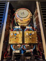
I ended up moving the driver boards from their mounting location on top of the channel boards, which was hard to access and work on, to a top mounted aluminum plate above the primary capacitors. I included a picture of the new mounting position for the driver boards in the amp I'm working on. I made other changes to try and improve the reliability of the amp. I changed Q4/Q6 out for 2N5415/2N3440 TO-39 transistors with heatsinks to improve their power handing capacity. I also increased the current through the VAS from ~7mA to ~11mA. R8 was also changed to a 12K/1W resistor. I also added DC rail fuses to both of the driver boards for safety purposes. You can see these in the pictures. For some reason White Audio decided that a single slow blow AC mains fuse was enough to protect downstream gear from catching fire in the event of a major failure.
In relation to the high DC offset. I've found that this amp seems quite prone to ground loop noise and this seems to mess with the DC offset. With my Audio Precision analyzer connected to the White Amp I always had 45 - 48mV of DC offset in both channels. This is even when I put some very well matched LTP pairs into the driver boards. When I finally finished with the amp and took it into my audio room and connected it up to my 2 preamps, an Acurus RL-11 & Adcom GFP-750, both of them gave me extremely low DC offsets in the 1 - 8mV range. You can try to install a well matched transistor pair into the LTP stage and see what happens, if its still high then try connecting it to a different preamp or piece of test gear to see if the DC offset drops appreciably. Most likely your amp is working fine, but you may want to make some changes to help with reliability.
From what I've seen White Audio made no changes to the driver boards component values between the high power and low power versions of these amps. It seems that they indiscriminately used the same driver boards on 50wpc Class A versions that had probably 35 - 40vdc rails and the high powered 200W+ versions with > 60vdc rails. This leads to problems with overheating on certain components for the higher powered versions like R8, Q4, Q6, in my schematic posted above, so keep this in mind if you see parts that look overheated or if the board seems cooked.
I ended up moving the driver boards from their mounting location on top of the channel boards, which was hard to access and work on, to a top mounted aluminum plate above the primary capacitors. I included a picture of the new mounting position for the driver boards in the amp I'm working on. I made other changes to try and improve the reliability of the amp. I changed Q4/Q6 out for 2N5415/2N3440 TO-39 transistors with heatsinks to improve their power handing capacity. I also increased the current through the VAS from ~7mA to ~11mA. R8 was also changed to a 12K/1W resistor. I also added DC rail fuses to both of the driver boards for safety purposes. You can see these in the pictures. For some reason White Audio decided that a single slow blow AC mains fuse was enough to protect downstream gear from catching fire in the event of a major failure.
In relation to the high DC offset. I've found that this amp seems quite prone to ground loop noise and this seems to mess with the DC offset. With my Audio Precision analyzer connected to the White Amp I always had 45 - 48mV of DC offset in both channels. This is even when I put some very well matched LTP pairs into the driver boards. When I finally finished with the amp and took it into my audio room and connected it up to my 2 preamps, an Acurus RL-11 & Adcom GFP-750, both of them gave me extremely low DC offsets in the 1 - 8mV range. You can try to install a well matched transistor pair into the LTP stage and see what happens, if its still high then try connecting it to a different preamp or piece of test gear to see if the DC offset drops appreciably. Most likely your amp is working fine, but you may want to make some changes to help with reliability.
Attachments

Great information - I did hook it up to my Outlaw 975 (easy to get to and runs on digital input, so fairly quiet) and I get 85mV on both channels after about 45 mins. of listening. So better, but still a little high. I will get some LTP transistors and do some matching and see if I can lower the offset by 50%+ and I'll be happy.
What are your thoughts and taking out the direct link of the Source leg and putting in a 0.22r I have on hand, to better measure the bias and less chance of one transistor hogging current? I don't want to alter the factory look, but I also want it to last for a long time without worry.
What are your thoughts and taking out the direct link of the Source leg and putting in a 0.22r I have on hand, to better measure the bias and less chance of one transistor hogging current? I don't want to alter the factory look, but I also want it to last for a long time without worry.
The DC offset in this amp when I 1st received it was quite a bit different, one channel was around 10mV and the other drifted quite a bit but was around 65 - 75mV on average. It wasn't until I changed the LTP's out with well matched parts that I started getting the matched DC levels of around 45mV for both channels. Once an XLR source is connected the offset drops to < 10mV now.
The fact you're getting the same mV on both channels tells me its likely a grounding/noise issue. Do you have any source with an XLR output that you can connect to it? The reason I ask is that my low mV offset numbers are when using the XLR input. I tested it again this morning, I tried pulling the XLR connections (from my Adcom GFP-750) and then putting a set of shorting plugs into the RCA inputs. With this config I get about 45mV on both channels, I also got about 45mV on both channels when connected to my AP analyzer via RCA. When connected to the AP using the balanced XLR connections it would drop the offset down to single digits. So connecting the inverted leg of the XLR to something seems to mitigate this issue. It's normally floating.
I don't see any problem with adding 0.22r resistors into the source legs. I know that the big benefit of laterals is the fact they do not need source resistors due to their positive temp coefficient, but four 0.22r resistors in parallel is like 0.055ohm of added output impedance. I'd say go for it and if for some reason it seems to affect the amps sound in a negative manner then remove them.
okay spent some time tearing apart my HT setup to borrow the balanced pre-amp to try your suggestion. There is not much change in the overall DC, with a minor difference channel to channel, right is still ~80mV with left dropping to ~70mV. So I think I will start with changing the LTP and see if I can't get the DC under 25mV with some closer matched parts.
Thanks for your assistance, now trying to get some ZTX657s that aren't from eBay - Mouser and Digikey are out of stock until 2024 - yikes!
Thanks for your assistance, now trying to get some ZTX657s that aren't from eBay - Mouser and Digikey are out of stock until 2024 - yikes!
good to know about the MPSA42s - I have some of those on hand. You answered my next question on the current of the LTP, so I will know what to match them at. Rails are +/-59 measured at the supply Caps. I just measured the DC after almost an hour of playing low volume music at they are, Right 75mV and Left 72mV so they have become more balanced channel to channel after more warm-up time.
With that high of a rail voltage I would install a 1W resistor into the R8 position if its not already. I would also install either new ZTX parts at Q4/Q6 because the old ones although functional they have been cooked for years. You can also make the switch to 2N5415/2N3440 at Q4/Q6. Central Semiconductor is producing these now and are available at Mouser. The nice thing about the TO-39 parts is that you can add a heatsink which massively improves their heat dissipation and should stop them from burning the boards.
- Home
- Amplifiers
- Solid State
- White Audio Labs B3 amplifier rebuild (Schematic included)