Parallel a 220R or so to the speaker output so the cap can discharge when no speaker is connected.

I found another power jfet but unfortunatly it does not have triode like curves.
The curves may varie a lot from batch having a 70ma turn on voltage of
-6 to - 14. In the few I bougth when I let them self bias with a 8 ohm resistor mine
acted like a rather nice 1.12 A CCS over a voltage range of 12 to 100 V . But I know
someone else here reported his didn't respond like this. The reason I wanted to
point this 190W $ 12 device is it biases a lot like a 2sk180 . and for early testing
like in that proposed source follower with the 300W light bulbe this cheaper device
might be a good subsitute.
Attachments
Like so. Nice to set it straight. (But please keep on correcting.)Parallel a 220R or so to the speaker output so the cap can discharge when no speaker is connected.
BTW, this front end could of course be the preamplifier. But I have a B-1 with unity gain, so somewhere the gain has to be developed. (Well... I also have a pletora of preamplfiers with gain.)
This is just a hastily simulation, e.g. I do not have 2SJ313/2SK2013 spice models, but neither do I have more of those MOSFETs so... The FQP3N30/FQP3P20 seems to be to some degree still available.
That's a mighty big transformer! Dual secondaries so I assume a stereo amplifier, and a very heavy one! 🙂

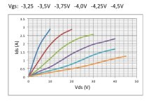
SIC power JFETs are certainly interesting components. The measurements you obtained unfortunately highlight their main limitation: It is difficult to select two components with similar characteristics. It is a pity. Few years ago I bought three JFET (UJN1208K). I was lucky, they are very similar.I found another power jfet but unfortunatly it does not have triode like curves.
The curves may varie a lot from batch having a 70ma turn on voltage of
-6 to - 14. In the few I bougth when I let them self bias with a 8 ohm resistor mine
acted like a rather nice 1.12 A CCS over a voltage range of 12 to 100 V . But I know
someone else here reported his didn't respond like this. The reason I wanted to
point this 190W $ 12 device is it biases a lot like a 2sk180 . and for early testing
like in that proposed source follower with the 300W light bulbe this cheaper device
might be a good subsitute.
This is an Ids/Vds graph. The linearity is definitely better than an IRFP9240.
Attachments
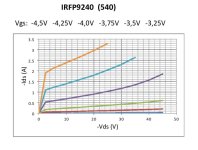
These curves show quite a bit of thermal runaway due to self heating during testing. This may add to the (alleged?) non-linearity. But linearity is usually not so much the point when it's about "triode" vs "pentode" curves.
It would be nice to test a batch of UJN1208K with temperature controled at a fixed value and then compare the curves.
It would be nice to test a batch of UJN1208K with temperature controled at a fixed value and then compare the curves.
Before carrying out the measurements I cooked the transistors at around 50°C. I interpreted the UJN graph as a FET that belatedly remembers that is a pentode.
The IRFP is not chosen at random. It is paired with the JFET for an DEF Amp (Vg=-4.1V, Vg=23V, Id=1.3A).
In the photo of my measurement system there is a THF-51S. Let's talk about SITs and therefore this is the Id/Vd graph. IT's definitely not accurate at high current.
The IRFP is not chosen at random. It is paired with the JFET for an DEF Amp (Vg=-4.1V, Vg=23V, Id=1.3A).
In the photo of my measurement system there is a THF-51S. Let's talk about SITs and therefore this is the Id/Vd graph. IT's definitely not accurate at high current.
Attachments
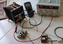

That's a good start, but the devices will heat up more at high power.Before carrying out the measurements I cooked the transistors at around 50°C.
I made a temperature controlled heater block to take measurements at fixed temperatures:
https://pypsucurvetrace.readthedocs.io/en/latest/
Just giving this a gentle bump. Ran across the box with these yesterday and realized it’s been a while since this project has been mentioned.
Any chance of a this one coming to fruition in the relatively near future?
Any chance of a this one coming to fruition in the relatively near future?
Last edited:
having any specific wish, still not covered around in last 5 years or so?

What exactly is it you are looking for? There have been a bunch of THF51 projects, and maybe there is one for you.Just giving this a gentle bump. Ran across the box with these yesterday and realized it’s been a while since this project has been mentioned.
Any chance of a this one coming to fruition in the relatively near future?
- Home
- Amplifiers
- Pass Labs
- While they last...