What is WRT? Could you explain this more clearly.
It's just an acronym for With Respect To
How can I select the power tube with out knowing what the grid voltage is? and it seems like the grid voltage depends on the driver tube.
You can't . And that's exactly why you're stuck . Too many unknows.
The OPT is 7k ohms.
No luck,again. 7k is an intermediate value which can work either with a 211 or 845 ! Optimal primary load impedance for a tube is not a fixed parameter and depends on many design factors such as: class of operation,bias,max.power transfer vs low distorsion,etc...
7k Being on the high side I would start with the assumption that the original tube was a 211 (which it probably was) and try different driver tubes to get the correct bias range (about -40 to -70VDC) and adjust it for a 50mA plate current @ 1.1Kv plate voltage which is close to 75% max. plate dissipation for a 211. At this point hopefully the amp should play fine and you can start measuring the performances and doing some fine tunning/tweaking if necessary.
TDSL Tube data [6FQ7]Could you give me a list of driver tubes that would work in place of the 6CG7?
Could you give me a list of driver tubes that would work in place of the 6CG7?
I will give you some useable tube suggestions to experiment with tomorrow. Also,it would be good to know if the driver (6CG7) is direct coupled to the preceeding stage or not. I'll try to figure this out from your (wiring) schematic diagram.
During the experimentation phase I would suggest you to temporary install a 10 ohms/1 watt resistor in the plate (or cathode return) circuit of the output tubes. These resistors will help protect the tubes and transformers if something go wrong. By measuring the voltage drop across the resistor you can also determine the actual plate current by Ohm's law. (0.5 volts across the resistor is equivalent to 50mA plate current) and adjust the bias accurately.
The grid voltage of the other side (Left) is -45 VDC with bias all the way up. This wouldn't work with the 211 at 1100 plate voltage. I don't think the 6CG7 is the right driver tube. Please help me figure out what driver tubes to use. I am working on the drawing, will post it asap.
Last edited:
During the experimentation phase I would suggest you to temporary install a 10 ohms/1 watt resistor in the plate (or cathode return) circuit of the output tubes.
Could you be more specific to what I need to do?
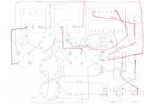
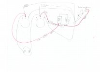
I am drawing a more detail layout of the entire amp.
The grid voltage of the other side (Left) is -45 VDC with bias all the way up. This wouldn't work with the 211 at 1100 plate voltage. I don't think the 6CG7 is the right driver tube. Please help me figure out what driver tubes to use. I am working on the drawing, will post it asap.
-45 VDC is too low for a 211 and way too low (dangerous) for a 845. Both tubes will be underbiased (= too much plate current) @ 1.1Kv plate voltage. For a 211 and with the correct driver tube in place a good target would be -60 VDC with the bias pot in midway position and about 20 VDC range above and below this reference (mid)point. Any positive bias value is suspect (wrong tube) as the designer of the circuit probably never allowed the bias adjustment for going into the positive region which is harmful for the tubes and surrounding circuits. Looks like the 6CG7 is not the original tube...
A detailed drawing of the circuit would be very useful...
For a 211 and with the correct driver tube in place a good target would be -60 VDC with the bias pot in midway position and about 20 VDC range above and below this reference (mid)point.
That is exactly what I am thinking.
A detailed drawing of the circuit would be very useful...
I am working on it.
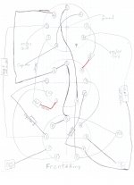
Here is how the grid voltage is affected by the driver tubes:
- without any tubes, grid voltage is -392 VDC, unaffected by bias adjustment.
- with just the back tube 6CG7 (the tube that has the grid wire connected), grid voltage is +50 VDC at highest bias setting.
- with back tube 6CG7 + middle and/or front 12AU7 tubes, grid voltage is -55 VDC.
- with just middle and/or front 12AU7 tubes, grid voltage is -392 VDC.
The 6CG7 is changing the bias from -73 VDC coming in from the bias pot to +50 VDC going to the power tube grid. This is done without the other two driver tubes.
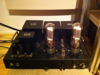
I got the amp working using the 845 tube.
I modified the grid voltage by changing the resistors. I got the Shuguang 845B running at about 70mA. The plate voltage is 1098 VDC and grid at -160 VDC
It is working great with 6CG7 in the back and 12AU7 in the middle and front sockets.
Thank you all for the help.
Stuart, let me know when you would like to come by and listen to my system.
Attachments
- Status
- Not open for further replies.
- Home
- Amplifiers
- Tubes / Valves
- Which tube does my amp use? 845 or 211