If your amplifier uses no NFB off the speaker side of the tranny, polarity is irrelevant. If you have NFB and your circuit oscillates, switch polarity 😉
Geek said:If your amplifier uses no NFB off the speaker side of the tranny, polarity is irrelevant. If you have NFB and your circuit oscillates, switch polarity 😉
I'm not sure it it uses negative feedback or not. It is a home-brew amp. So there is no schematic. The former owner attempted to recap it and to install new speaker binding posts and input jacks but gave up on the task and left lots of wires disconnected, components removed, etc.
Since polarity makes no difference if there is no NFB, maybe I should just wire it without NFB. What effect would this have on its performance?
And if I do wire in NFB, should the connection be made from the + binding post through a 5.6K resistor and a 390MMF cap to G2 of the EF86? (I'm assuming, due to its tube configuration, that the amp is based on the Mullard 5/20 design).
Alright, now we need to know a bit more.
What tubes does the amp use? If a pentode like 6V6 for output, is there a resistor or jumper connecting pins 3 and 4? If so, it doesn't need NFB. If not, it probably does, or was designed to - is there anything connected to the speaker terminals besides the transformer wires? Say, a resistor with capacitor in parallel? That would be for NFB.
Easy enough anyway, as Geek says - switch polarity if it oscillates. If it oscillates either way.... you have worse problems
<Edit for an edit. Durn simulposters you!>
The exact NFB network required depends on overall gain, setup, desired NFB, etc. I'd need a circuit to say for sure.
Tim
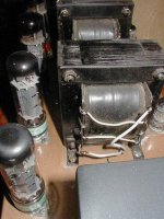
It uses (per channel) two EL34, one EF86, one 12AX7, and one GZ34. Please see the enclosed photo of the output tube wiring. I received the amp with a small box full of caps, resistors, that had been removed, so I'm not sure what (if anything) it had connected to the speaker terminals.Sch3mat1c said:Alright, now we need to know a bit more.
What tubes does the amp use? If a pentode like 6V6 for output, is there a resistor or jumper connecting pins 3 and 4? If so, it doesn't need NFB. If not, it probably does, or was designed to - is there anything connected to the speaker terminals besides the transformer wires? Say, a resistor with capacitor in parallel? That would be for NFB.
Easy enough anyway, as Geek says - switch polarity if it oscillates. If it oscillates either way.... you have worse problems
<Edit for an edit. Durn simulposters you!>
The exact NFB network required depends on overall gain, setup, desired NFB, etc. I'd need a circuit to say for sure.
Tim
Attachments
If you have Mullard's schem,you can rebuild it as a Mullard 5/20!
About the OPT connections,I think it's not too difficult to understant the primary connections.
About the secondary ... where are the grey cables going??
Maybe these are for the speaker terminals.
So do as Geek says.
I think the other are connections to achieve 4 , 8 or 16ohms.
About the OPT connections,I think it's not too difficult to understant the primary connections.
About the secondary ... where are the grey cables going??
Maybe these are for the speaker terminals.
So do as Geek says.
I think the other are connections to achieve 4 , 8 or 16ohms.
The output (secondary sides) of the OPT have only two grey wires that presently are unconnected. So, these OPT do not have the usual 4-8-16 ohm taps. The Mullard 5/20 schematic says that R13 and C9 (feedback loop components) are to be "chosen to match speaker as follows: 3.75 ohm speaker - 3.9K and 470pF respectively; 7.5 ohm speaker - 5.6K and 330pF; 15 ohm speaker, 8.2K and 220pF.
The Mullard design shows C10 and C11 (EL34 control grid bypass caps) as 0.5µF 350v; this amp has 0.1µF 1000V oil cans.
The Mullard design shows C10 and C11 (EL34 control grid bypass caps) as 0.5µF 350v; this amp has 0.1µF 1000V oil cans.
I have tried running the amp bypassing the feedback circuit (the 5.6K resistor and 390MMF cap for each channel) and the result is that it works - with no howling, oscillation, etc., but the gain is far to high and the sound even with the preamp volume control way down is a bit harsh.
The output transformers, with two leads coming out of the secondary side of each, are a mystery to me.
Would it make sense to try to run EL34 tubes in triode mode? As I understand it, that would decrease the gain. For such a set up would I simply bridge the G2 screen grids and the anodes? Would I keep the present 0.1MF 600v cathode bypass caps and the 470 ohm cathode bypass resistors or would I need to change the values?
The links on the output transformer suggest it has several secondaries, connected in series. You could take 4/8/16 ohms taps off those junctions. I suspect it will be set up for 16 ohms, what impedance speakers are you using on it?
One secondary lead from the output transformer should be grounded, the other is the speaker + connection.
As previous posters have said, you should connect the feedbach resistor from the + speaker output, to the input tube, at the junction of the two cathode resistors. If it howls, reverse the output transformer secondary leads.
If I were you, I would study the Mullard 5-20 schematic and simply copy that. You will notice that the input tube has two cathode resistors, one of ~100 to ground, the other several Kohms to the tube. The junction of these is where you atach your FB resistor going to the + speaker terminal.
Triode mode will not decrease gain, just lower the power. Ie it will still be a small movement on the volume knob for loud output, but distort more easily. Triode mode is a 200 ohm resistor from screen (g2) to anode. I would be suprised that the el34s have 0.1 cathode caps, that sounds like a coupling cap to the grid (g1) to me.
BTW those are some mullard el34s in the background I think... 😎
One secondary lead from the output transformer should be grounded, the other is the speaker + connection.
As previous posters have said, you should connect the feedbach resistor from the + speaker output, to the input tube, at the junction of the two cathode resistors. If it howls, reverse the output transformer secondary leads.
If I were you, I would study the Mullard 5-20 schematic and simply copy that. You will notice that the input tube has two cathode resistors, one of ~100 to ground, the other several Kohms to the tube. The junction of these is where you atach your FB resistor going to the + speaker terminal.
Would it make sense to try to run EL34 tubes in triode mode? As I understand it, that would decrease the gain. For such a set up would I simply bridge the G2 screen grids and the anodes? Would I keep the present 0.1MF 600v cathode bypass caps and the 470 ohm cathode bypass resistors or would I need to change the values?
Triode mode will not decrease gain, just lower the power. Ie it will still be a small movement on the volume knob for loud output, but distort more easily. Triode mode is a 200 ohm resistor from screen (g2) to anode. I would be suprised that the el34s have 0.1 cathode caps, that sounds like a coupling cap to the grid (g1) to me.
BTW those are some mullard el34s in the background I think... 😎
Hi,
It reads Philips Miniwatt through my glasses....Not that I wear any...
Why redo the circuit? It seems to be working O.K, the distortion without NFB is what you'd expect from an amp from that era, no?
Cheers,😉
BTW those are some mullard el34s I think...
It reads Philips Miniwatt through my glasses....Not that I wear any...
Why redo the circuit? It seems to be working O.K, the distortion without NFB is what you'd expect from an amp from that era, no?
Cheers,😉
Philips owned mullard so I am guessing they are rebadged mullards (or rather mullards are rebadged philips) 😛
Hi,
Nope....These are true Philips EL34s Made in Holland.
............Of course, we could always ask the owner to tell us the factory codes....
Cheers,😉
Philips owned mullard so I am guessing they are rebadged mullards (or rather mullards are rebadged philips) 😛
Nope....These are true Philips EL34s Made in Holland.
............Of course, we could always ask the owner to tell us the factory codes....
Cheers,😉
All four of the output tubes were Philips EL34 Miniwatts when I got it, but 2 of them tested bad. BTW, these are not identical. One with a brown base and flat top has "xf2" above "5BD4" in small lettering next to the base. The other with a black base and a more rounded top has "^13" above "X9G". I replaced these with a matched pair of Electro Harmonix.
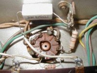
A .1µF 1000v cap goes from ground to the control grid (pin 5) with a 2.2K one-half watt resistor connected from pins 5 to 6. A 47µF 350v electrolytic cap is connected from ground to pins 1 and 8. Pin 4 is connected through a 1K 2 watt resistor to the OPT primary.
The speakers I am using are AR4x (8 ohms).
While running the amp today, both 100 ohm 1 watt resistors (R5) that go from ground to a 47µF 50v cap and 2.2K one-half watt resistor (R4) into the cathodes of the EF86 tubes fried. Wish I knew why. The two tubes still both test fine.
I would not run the amp at all until you find out why it has burned resistors.
I suspect you are reading the numbers on the sockets wrong, as there should be no cap to ground from the g1 grid of the EL34!!!
The number of the pin is above it on most sockets...
Check whether it is consistent with the mullard schematic...
Also download the tube database software from www.duncanamps.com and check the pins.
Originally posted by billinchile
A .1µF 1000v cap goes from ground to the control grid (pin 5)
Well that definitly isn't right! Are you sure it's an .1uF, maybe it's an 10pF or 100pF. Pin 6 would be where the coupling cap from the driver would connect to, the 2.2k resistor being the grid stopper. Is the 1k resistor going to a screen tap on the OPT or the same connection as the plate (pin 3)?
While running the amp today, both 100 ohm 1 watt resistors (R5) that go from ground to a 47µF 50v cap and 2.2K one-half watt resistor (R4) into the cathodes of the EF86 tubes fried. Wish I knew why. The two tubes still both test fine.
Look and see what's connected to EF86's grid, screen grid or whatever else is connected to those resistors at the cathodes. Definetly sounds like a fixer-upper or a start-over from scratch!

Wayne🙂
A few of the connections are difficult to see because they are made on the underside of a mounting board that I can't access.
You are correct, of course; the cap in question is not attached to ground, but rather goes between the plate of the 12AX7 driver to pin 6 of the EL34 which is connected to pin 5 through a 2.2K resistor. When I got the amp, these caps were .1µF 1000v "oil caps" (or so it says in Spanish) I replaced them with the type shown in the attached photo. Was this a mistake? I'm not sure why the builder chose the oil caps; the Mullard 5/20 part list/ schem shows C10 and C11 as a .5µF 350v "paper caps".
The screen grid (pin 1) of the EF86 is connected to the tube's cathode (pin 3) through a .05 cap. Pin 3 is bridged to pin 8 - the suppressor grid - and pin 8 is connected to the 100 ohm resistor that burned by way of a 2.2K resistor and a 47µF 50v cap.
Attachments
cogsncogs said:
Is the 1k resistor going to a screen tap on the OPT or the same connection as the plate (pin 3)?
Wayne🙂
The 1K resistor goes from pin4 to a screen tap on the OPT.
Originally posted by billinchile
I'm not sure why the builder chose the oil caps; the Mullard 5/20 part list/ schem shows C10 and C11 as a .5µF 350v "paper caps".
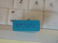
A-lot of people like the sound of oil caps! 😀 Paper caps should be replaced, we have much better caps to choose from these days. I couldn't make out the voltage of the cap in the pic you posted. What's the voltage rating? 630V would be just about ideal, 400V min.
When rebuilding an amp such as this, I would use fairly cheap parts (not too cheap of course!) like Solen caps or better, Sprague Orange Drops (polypropylene, tin & foil) to replace all the coupling caps. 1-2W metal oxide resistors when and after you do some measurements and check all of the power supply caps. More than likely (don't know the age of this amp or the parts therein) the electrolyte in the caps has dried up. Then after you get the thing going, then go for the the exotic parts.
and pin 8 is connected to the 100 ohm resistor that burned by way of a 2.2K resistor and a 47µF 50v cap.
Pin 8 should be connected to the 2.2k, 47uF parallel combination which is connected to the 100 resistor to gnd. The feedback connection would, (if it had one, which seems to be the case here) be at the junction of the 2.2k, 47uF combination and the 100 ohm resistor.
A few of the connections are difficult to see because they are made on the underside of a mounting board that I can't access.
I think I'd be doing some ACCESSING! 😀
Hope this helps
Wayne 🙂
You are right, of course, Wayne. Pin 8 of the EF86 is indeed connected just as you describe.
I don't know the the voltage rating of the cap either. But that's because I don't understand the code on it: it looks like (sigma) LBPP 0.1/22.5 (over) 1JK2 L9
These are called "WIMA" caps, I believe. I'm not at all sure it they are appropriate for this application. But they had the overpowering advantage that they were were available. Please understand that obtaining Solens, Orange Drops, metal oxide resistors, and all the other stuff that I drool over when reading the likes of the AES catalog represent a major effort. It would be great to just be able to call an 800 number, give credit card information and have the components I want in my mail box shortly thereafter. But the reality is that living a the bottom of the world and trying to obtain the wonderful tube sound that I love are often incompatible. "Assessing" would involve unsoldering a couple dozen connections in order to be able to view the underside of the board. So I have resisted it.
- Status
- Not open for further replies.
- Home
- Amplifiers
- Tubes / Valves
- Which trans wire is which?