Hi FroggySeven,
You could probably reduce the size of the box by giving up a little bit of low frequency extension (still goes well below your initially stated goal of 30Hz); but you'll be picking up a bit more excursion capability at the low end. I'll attach a Hornresp example. The slight peak below 30Hz will disappear after the box is properly stuffed. Also, take a look at permo's thread:
http://www.diyaudio.com/forums/subw...band-w8q-1071f-8-x-12-box-reccomendation.html
From that you should be able to figure out a layout, and once you have determined your final external dimension bjorno can help you with determining the details.
Regards,
Attachments

Since you are limited on power, I would get the biggest ported sub I could fit.
The dayton TIT400 will extend low and play loud with your amp. The dayton 15 in a 150L box would be awesome.
The dayton TIT400 will extend low and play loud with your amp. The dayton 15 in a 150L box would be awesome.
Last edited:
Member
Joined 2012
spinMonster : probably a good idea, thanks. But I have already bought the Monacors...
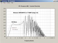
tb46 : I like those "only 130L" a lot, 'cause the upper crossover frequency rises too.
But for the peak at 30Hz : how stuff material coud be efficient at a such frequency !!???
tb46 : I like those "only 130L" a lot, 'cause the upper crossover frequency rises too.
But for the peak at 30Hz : how stuff material coud be efficient at a such frequency !!???
[ this first message have been edited twice :
1/ Considering the following answers (thanks a lot for your help 🙂 !!! )
2/ when I've made my decision]
[....]
Less than 300€ for one speaker, and down to 30Hz would be nice.
As I will use an equalizer, "down to 30 Hz" doesn't mean -3db but just the max SPL between 30 & 40Hz with 250W@4ohms !
If you're after max SPL between 30 and 40Hz, consider a (BIG) horn. Here's one for the Monacor SPH-390TC:

118dB from a single sub, with -3dB point at 30Hz.
Xmax limited at 125W@4Ohm input, which is nice because I think having some headroom in your amplifier is a good idea. (typically about 30-100% power headroom).
Beware this is a big box, aimed to maximize SPL to 30Hz. (about 100cm x 60cm x 50cm is how I would fold it). Plywood would cost you about 80€ here (nor sure how french prices are), so still within your 300€ budget
And, typically for tapped horns, you will have to delay your main speakers by a few ms for everything to play in sync.
Just an alternative consideration I'm throwing out there.
Hi FroggySeven,
Post #23: "...for the peak at 30Hz : how stuff material coud be efficient at a such frequency..."
Reading through the thread linked in Post #21 will give you an idea as to the type, density and application of the stuffing. This is based on the work and spreadsheet by Martin J. King - http://www.quarter-wave.com/ - I think this is the program bjorno is using to evaluate the effectiveness of the stuffing. Bjorno noted before, that peaks up to ~3dB can be handled with this method, so this one should not be a problem. But I hope bjorno will chime in on this.
Regards,
Last edited:
Hi Oliver,
Just a notification about the inductance value for two voice coils in parallel. If you look on the Monacor website you can find the correct values in relation to the setting of the Voice Coils.
The most practical method for inductance in parallel:
(Le1 + Le2) : 2
The most practical method for inductance in series:
(Le1 + Le2) x 2
I used the word 'practical' because the correct formulas are:
Theta = Impedance Phase Angle
Lvc = VC Inductance
X = Z x sin(Theta)
Cmes = Mms / BL^2
Xl = X + [1 / (2 x Pi x f x Cmes)]
Lvc = Xl / (2 x Pi x f)
Note: these formulas only work for drivers in free air where the air-mass is static (constant).
--------------------------------------------------------
Most modelling software use a static value for Le while Le is also a dynamic value down low in an acoustic load. Especially dynamic for horn-type subwoofers where the 'extra' acoustic air-mass (to have a lower Fb in relation to Fs), is added to the Mms of the driver. The inductance of the Voice Coil can increase up to four times the original value.
Maybe this puts a light on things ;-)
Last edited:
Hi Djim,
I just worked with bjorno's numbers. As to your formulas, the first two are definitely wrong, something must be lost in the translations; anyway I'm once again on the run.....
Series and parallel inductors : INDUCTORS
Regards,
I just worked with bjorno's numbers. As to your formulas, the first two are definitely wrong, something must be lost in the translations; anyway I'm once again on the run.....
Series and parallel inductors : INDUCTORS
Regards,
Hi Oliver,
Your linked examples have three major differences. The first one is that they are all about air-inductors. The second difference is that they are all based on circuits of two independent inductors. The third difference is that the value of all examples is only the product of an electrical circuit.
In dual Voice Coil drivers the coils have a core so they are not functioning as air-coils. They are not two independent coils, but are functioning as one (since they are electrically too close to be independent). The inductance of a Voice Coil is the product of an inductance in an electrical circuit (L1) and an inductance from an acoustic circuit (L2).

I know how things can get lost when you are in a hurry;
Your linked examples have three major differences. The first one is that they are all about air-inductors. The second difference is that they are all based on circuits of two independent inductors. The third difference is that the value of all examples is only the product of an electrical circuit.
In dual Voice Coil drivers the coils have a core so they are not functioning as air-coils. They are not two independent coils, but are functioning as one (since they are electrically too close to be independent). The inductance of a Voice Coil is the product of an inductance in an electrical circuit (L1) and an inductance from an acoustic circuit (L2).
I know how things can get lost when you are in a hurry;
Last edited:
Hi Djim,
Here is a link to a paper I found helpful, "An Improved Electrical Equivalent Circuit Model for Dynamic Moving Coil Transducers":
http://www.tymphany.com/files/resources/papers/AES122nd-Impedance.pdf
I would expect the term Le, as used in e.g.: Hornresp, to be a measured blocked inductance.
I looked at the T/S parameters again (e.g.: Post #21), and the Re should have been 3 Ohms. Changing the Le from 0.65mH to 1.3mH makes little difference. The model seems to be sensitive to added resistance in Rg.
Anyway, thanks as always,
Regards,
Hi Oliver,
David said that HornResp uses a static value for inductance independent of frequency. The reactance in HornResp is calculated by [2 x Pi x f x Le].
The BL is 16.72 Tm for the SPH-390TC
(you might find this model interesting since it includes the acoustic issues; It's from R. Römer and G. Schwamkrug)
Last edited:
Member
Joined 2012
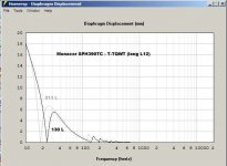
Thank you for the line charts
uhh... I am not sure... does it mean that for 130L, Bass reflex is MUCH better
for group delay, impulse response and even global frequency response for bass ?
By the way : 130L is not Bessel volume, isn't it ?
Would group delay and impulse response be even better with 150L ??
uhh... I am not sure... does it mean that for 130L, Bass reflex is MUCH better
for group delay, impulse response and even global frequency response for bass ?
By the way : 130L is not Bessel volume, isn't it ?
Would group delay and impulse response be even better with 150L ??
Last edited:
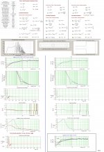
Hi FroggySeven,
Post #32: "... does it mean that for 130L, Bass reflex is MUCH better for group delay, impulse response and even global frequency response for bass ?"
In Post #21 I tried to show, that in my opinion the enclosure size for bjorno's T-TQWT could be reduced.
Anyway, using Hornresp to model the T-TQWT family of enclosures is only a convenience, as it seems to give an adequate idea of the raw frequency response. The response, especially the pipe resonances changes drastically when the enclosure is properly treated with sound absorbing material. Bjorno models this with MJK's MathCad software (see: link in Post #25). The frequency response is smoothened, and the impulse response ends up to be closer to that of a closed box. The pipe resonances in a bass reflex will not be attenuated as effectively; the resonances of a 15cm diameter x 50cm long duct port will definitely be audible
Bjorno has shown a large number of examples here on diyaudio, and people who have build these enclosures have given very positive responses. The biggest difference seems to be an audible improvement in sound quality. Naturally, this is a somewhat subjective criterium. Here are two examples of threads on this subject:
http://www.diyaudio.com/forums/subwoofers/188283-fiddling-hornresp-peerless-831759-a.html
http://www.diyaudio.com/forums/subw...band-w8q-1071f-8-x-12-box-reccomendation.html
Let me add, that I do not yet have personal experience in listening to T-TQWTs. I find them interesting, and I have been helping out with the folding and drawing of boxes. I don't have MathCad, nor do I have the obviously extensive experience with this type of box that bjorno brings to the table. My past experiments with transmission line enclosures (and numerous BRs) leads me to believe, that a properly treated transmission line (or any one of what we could now call the MJK mass-loaded family) is superior in sound quality to a bass reflex.
Hopefully borno will find the time to add his comments to this.
Regards,
Last edited:
Hi FroggySeven,
Somehow I get the feeling my intentions are interpreted differently from what I meant. I showed the impulse response just to consider (like its phase behaviour) and not as a ‘battle’ argument; In reality the impulse responses are often more the result of the location within an acoustic space (room acoustics).
I do agree with Oliver that you should wait until Bjorno is back since he is the (only?) person here on DIY who can show you advanced modelling of T-TQWT type enclosures. I am not ‘battling’ over the qualities a proper worked out T-TQWT can offer. However, I think it is more than fair to show the disadvantages of a loss of 2dB to 3dB @ 1W/1m and 4dB to 6dB @ Xmax in relation to basreflex.
Which considerations you should make is a personal matter and probably comes down to dynamics versus overall quality. I don’t favour any design over another since I strongly believe that for each type there are advantages and disadvantage and limitations. Each should be judged by personal preference in a specific situation. Another design, like a Tapped Horn as suggested earlier by jwmbro is possible but would end in a much larger enclosure that doesn't seem to fit in your demands.
To answer your earlier question about PPSL, it’s nothing more than a special arrangement of two drivers in one enclosure that could be of almost any type. One driver should face the magnet of the other driver and preferable share the same acoustic volume to suppress non-linear movement of the cones. Whatever enclosure type you consider, I can recommend this configuration because of the reputation of your drivers. You can use the search button by entering 'PPSL' to find more information on DIY forum.
Last edited:
One small note: If you can bridge your two plate amplifiers (500W @ 8Ohms) you can consider an improvement over the excursion and the impulse behaviour by connecting the VC’s of each driver in series (16Ohms). Wire each driver independently to your amplifier and connect them in parallel to get 8 Ohms for your bridged plates. Of course, such arrangement should be decided before designing the final enclosure(s) because of the changing parameter inputs.
Hi,
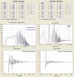
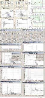
I'm almost back again...50% ?...😀. Ive noticed that my T-TQWT suggestion had a Re = 4 Ohm but should be = 3Ohm = as a result = minor FR difference but more important is that the advertised T/S is not consistent.
A consistency check can be found in the first submitted picture.
I fully agree with tb46 in post# 33 as the comparison made with a BR at 1W only show the speaker sensitivity and empty box behavior differences.
A more useful comparison is shown in the second of pictures.
If comparing the impulse response (always above + 10 mS where it matters its clear that the BR more or less would have an easy heard 'signature' at higher amplitudes even if using a LPF at or above 80 Hz.
Note: The tb46/Djim ? T-TQWT compared with the BR is xmax limited whereas the BR is port noise limited at higher SPL.
The T-TQWT sub can at max be XO:d at 145 Hz using a 24 dB/octave LPF(= max if Hi-Fi where 250 Hz would be 20 dB down) but not the BR that for Hi-Fi use should IMO use a XO < = 120 Hz.
b🙂
Attachments
Hi Bjorno,
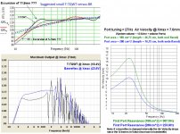
Maybe I am wrong but why do you compare the outputs based on different excursion values or without notification? See picture with added possible(?) values.
If there are worries about port noises as result of the air velocity, you can always improve it by using internal damping and/or make the port area as big the mouth/port of the T-TQWT (length compensation and volume compensation needed). Internal damping would also improve impulse response of a basreflex.
Attachments
Member
Joined 2012
@ bjorno
Would you be so kind to model a TH tuned around 18hz? I have a sph390tc and a second one coming soon. I would like to build 2 tall subs with a small footprint. Much appreciated!
@ FroggySeven
What did you end up with?
Would you be so kind to model a TH tuned around 18hz? I have a sph390tc and a second one coming soon. I would like to build 2 tall subs with a small footprint. Much appreciated!
@ FroggySeven
What did you end up with?
Do you see the "RIP" under Bjorno's name?
That means that sadly he has passed away, therefore will not be able to help you.
That means that sadly he has passed away, therefore will not be able to help you.
- Home
- Loudspeakers
- Subwoofers
- which subwoofer for 250W@4ohms class D amp?