Hello!
I'm currently in the planning phase of the design of a car amplifier. I want to use the TPA3255 as the amplifier and plan to use it at its full potential (600W). As the TPA is ~90% efficient, I want to supply it with a 700W supply.
The first option would be a boost converter, as demonstrated in the PMP11769 design by TI. At a minimum input voltage of 9V (lowest voltage a lead-acid battery can go, I also want to use it in a boombox) and a output voltage around 53.5V, the switching losses would be 250kHz * 53.5V*(700W/9V)=20W if I was switching at 250kHz and with 10ns rise and fall time for the switching transistors. Adding conduction losses (assuming two phases, that causes the /2, *2) we get (assuming Rds_on=10mOhm): (700W/9V /2)^2*2*10mOhm=30W conduction losses. That's a total of 50W losses, not considering reverse recovery of the synchronous FET body diode and inductors in the system.
I looked into other topologies and found the resonant boost converter. It doesn't really have any switching losses, allowing for a lower Rds_on (since switching times are not as critical). The caveat is, that in that topology, the voltage stress on the FET is very high (Vfet = Vout*Iin+Vin =over 300V for my specs). This could be contained by using a multiphase version of the resonant boost.
Another option would be a cuk converter, but with the output in series with the input (as the output is a negative voltage, the + of the output and the - of the input are the same). This way, the cuk converter doesn't have to carry the entire 700W. I am still evaluating losses for this version.
My question: What are the topologies normally used for 500W>= car amps? In a video about the PDX-M12 I saw 40V MOSFETs, suggesting an isolated topology or something similar?
I'm experienced in power electronics (but higher power, around 50kW for motor drives, so my cooling is normally done with water...), so I'm not afraid of venturing into new topologies^^
Last edited:
Anything current fed is nice because input filtering is easier. Like as not TI would have given you the best bang they can do for their buck. Your output voltage is greater than their design @54V vs 36V but it is specified for a 50V load dump. You'll know more about such things than me but the automotive environment can get nasty. Based on that alone I would be specifying 60V plus devices which may well be what TI are using anyway... oh they are happy with 50V. Car audio generally uses a push-pull convertor and relies on leakage inductance in the main transformer as something else to blow things up. You might consider a current fed push-pull boost, overlapping drives clamp to output, but it does not really give you anything over the TI solution other than an extra transformer and some more headaches, might save you load dump to the output since that should be regulated out. AFAIK Cuk suffers from twice the peak currents and/or twice the peak voltages in the power devices and you have to be happy shunting 50A/100A square wave currents through capacitors.
...
...
Attachments

Thanks for the reply! I guess I'll look into push-pull converters then.
As for the Cuk converter: Wouldn't it have a relatively smooth input current waveform as that's the entire point of the thing?
As for the Cuk converter: Wouldn't it have a relatively smooth input current waveform as that's the entire point of the thing?
Yes. Cuk has continuous input and output currents. Every time I looked at one however I fell into all sorts of problems with untamed resonances which resulted in glowing resistors in damping networks. 🙁
In respect of my guess at the push-pull boost one of the things I was trying to avoid was overvoltage on the mosfet drains due to leakage inductance. Nominally you still need a VDS rating of at least 2VIN which really gives no benefit over and above the TI note but I guess it might be possible to play with turns ratios and get below that.
Second guess...
...
Attachments
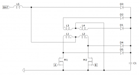
As I see it, the leakage inductance only causes spikes on the drain of the MOSFET, but this only affects the voltage rating, as this is not a permanent voltage. The switching loss is still merely affected by Vin as opposed to the boost converter, where the switching loss of the MOSFET is Vout*Iin
EDIT:
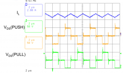
Here is a 250W reference design for a push-pull converter by TI: http://www.ti.com/tool/PMP11186
It's got a peak efficiency of 88% (going by only FET losses, a dualphase boost would have around 95%; the inductors wont have much loss, RedExpert by Würth gives me an approximate 1.2W per inductor), I'm going to calculate where all those losses come from (transformer?).
EDIT:
Here is a 250W reference design for a push-pull converter by TI: http://www.ti.com/tool/PMP11186
It's got a peak efficiency of 88% (going by only FET losses, a dualphase boost would have around 95%; the inductors wont have much loss, RedExpert by Würth gives me an approximate 1.2W per inductor), I'm going to calculate where all those losses come from (transformer?).
Attachments
Last edited:
Yes you will lose in the transformer but it is more likely RMS currents. Look at the input filtering compared to boost. Input current is discontinuous and the peak switch and therefore RMS values are likely to be much higher.