Thanks for the input.
OK, I will probably not try the aperiodic venting anyway.
If running straight powering, is using one single volume for all 20 drivers still a very bad thing? Won't standing waves in the enclosure be a problem anyway, just at different frequencies depending on the size of the enclosures?
Bjorno,
What is the main advantage of using a bessel array for the tweeters instead of just using one tweeter? The bessel array is meant to get a number of drivers to acoustically behave as one point source, right?
maghen said:
If running straight powering, is using one single volume for all 20 drivers still a very bad thing? Won't standing waves in the enclosure be a problem anyway, just at different frequencies depending on the size of the enclosures?
Right;
frequencies will be different.
Wavebourn said:
Right;
frequencies will be different.
Yes, bigger box = lower frequencies I assume. Is "different" bad when it means lower?
Lets just say 1.8 meter tall - what frequency might that be ? well, if drivers dont say much at this frequency you may not notice it, hard to say
You can prevent it with shelves on the back between each driver .... they only need to reach to drivers magnets .... should be plenty of space fore that 😉
You can prevent it with shelves on the back between each driver .... they only need to reach to drivers magnets .... should be plenty of space fore that 😉
maghen said:
Yes, bigger box = lower frequencies I assume. Is "different" bad when it means lower?
I tried both ways but did not hear differences. I use line arrays on concerts so each time use a 31 band EQ to equalize the whole loop between large diaphragm condenser mics and line array speakers. No differences in EQ settings for both versions of speakers. However, surfaces are well damped by linoleum (heavy!!!), a volume is well damped by a memory foam (the best material I've ever seen).
(BTW, unfolded they are exactly 1.8 meters tall! I.e. 30" each half ) 😀
tinitus said:Lets just say 1.8 meter tall - what frequency might that be ? well, if drivers dont say much at this frequency you may not notice it, hard to say
You can prevent it with shelves on the back between each driver .... they only need to reach to drivers magnets .... should be plenty of space fore that 😉
I will probably manage to put in some dividing walls. The fact that I already cut the holes, and the hole-array is shorter than the enclosure length, complicates it a bit though... (I will have to make slanting or "stepped" internal dividing walls to keep all part-enclosures the same volume.)
Anyway, I'm still curious about what causes standing waves of certain frequencies. And the effects of having many drivers in the same enclosure.
- Is it the length of the enclosure that determines the standing wave frequency, or is it the volume?
- Are there other reasons than standing waves of lower frequency for not using too many drivers in the same enclosure?
Thanks,
/Magnus
Anyway, the build is progressing. Does anyone have comments regarding my choice of driver for the bass uits? (sealed ~18l enclosure for an 8" Peerless SLS-213-830667)
I'm very found of seald enclosures, but for a bass unit? Please comment!
/Magnus
I'm very found of seald enclosures, but for a bass unit? Please comment!
/Magnus
tinitus said:Lets just say 1.8 meter tall - what frequency might that be ? well, if drivers dont say much at this frequency you may not notice it, hard to say
You can prevent it with shelves on the back between each driver .... they only need to reach to drivers magnets .... should be plenty of space fore that 😉
Around 94 Hz (?) F=340/3.6
Since I will mainly use these drives above this frequency, I would have thougt that dampenig this single enclosure would be better than parting it into several smaller units with "standing wave frequencies" in the middle of the range for the speakers.
Since I'm not any expert I will probably still follow the advice, but I'm still curious about the theories.
Standing waves at low frequency you can do nothing about .... if your mids only play down to 150hz, you could still risk a 100hz standing wave
And I would say that "standing waves" at higher frequencies are much less a problem
Stuffing only works at higher frequencies ... and I really dont like too much stuffing as it is .... muffles the sound, bass too
BTW ... I have found that "tar" impregnated hamp-fiber is VERY good ... just a very little amount, and the midrange wont get "muffled" like it happens with most other kinds of stuffing
stuffing
I glued the last sides of the cabinets today.
For dampening I have used a layer of "wavy" foam material (see pic) on the rear wall and one layer of 300g/m2 polyester wool in front of that. This leaves the backside of the front baffle and the front part of the side walls bare. Is this a bad thing?
I can still add a thin "carpet" to the side wall surfaces through he driver holes if necessary. (for instance pieces of IKEA's "Barrit" as Bjorno suggested)
Comments?
Attachments

Newbie alert....
I've read this whole line array forum knowing I want to build one but not knowing want not to do. This stuff is very complicated but I know in the end, it is the wall-of-sound I want. I just switched from 27 years of listening to "Maggies" to a single 8" full-range Fostex BIB 7 feet tall. They're sweet but there just isn't enough air moving to feel like "you're in the room with the players".
My problem is that, having read all the papers and waded through this mountain of information, I'm still not sure I understand why stacking 6 6.5 inch full-range Fostexs in a 7 foot sealed box is a bad idea.
Maghen,
In my experience the aperiodic approach is the only way to keep the volume requirements for the M drivers at a manageable size, making the array as slim as possible, not too deep and without bad transient behavior as the high Qtc driver value otherwise will ensure in a too small box.
Installing a lot of drivers = 👎 in the same closed enclosure makes a multi freedom of n degree system and not a good idea for drivers with thin paper membranes especially in a closed box.
There will be interaction if the drivers are mechanically different i.e. if the fs and the suspension differs as they do within a batch of low cost drivers even if from the same production lot.
See the animated system freedom of two degrees coupled oscillators and try imagine what happens when 👎 drivers all slightly off specification is put in a long narrow box where also the acoustic load behind each driver is different but box position symmetric, hence the action from the many different ‘stretchy cords’ that must exist in a box with many drivers sharing the same volume:
http://www.kettering.edu/~drussell/Demos/coupled/coupled.html
more:
http://www.kettering.edu/~drussell/Demos/multi-dof/multi-dof.html
In my opinion a short Bessel array (5- 7 T-drivers) behaves as a good single point source if listening at 10(20(opt=minimum ripple)) x array-length = 10(20opt) x (4-6) x 1.5” = 5(10opt)-7.5(15opt) ft or beyond.
Phase issues (still holds the demand for flat FR) can be ignored and of minor importance if the Bessel array is crossed over above about 1.5- 2 kHz where the dispersion will be at least as wide for a single driver, horizontally or vertically.
Horizontal phantom MAA (minimum audible angle) is as for a single driver and experienced for the verticals too but if correspondingly 5-7-(8) drivers are configured in a straight array, the vertical MAA is wider but will be blameless to about 7-8 (>8) kHz if 1.5” drivers are used.
MAA? See:
http://www.diyaudio.com/forums/showthread.php?postid=1209527#post1209527
For a good design, choosing a crossover point here restricts the horizontal c-c distance between an M and T driver to < = 0.1 m* or about 4” if suppressed blameless horizontal secondary lobes of < = 12 dB is the minimum requirement as it should be in my opinion.
*Obviously this holds also for a single 4” T driver and a <= 4” M array drivers if minimum possible horizontal c-c distance is secured.
Then the horizontal azimuth coverage for a vertical oriented M-T array will be about + - 30 degrees at the – 3dB points if a second order LR filter is used.
The lobe levels, symmetrically at 60 degrees of axis would then be 12 db down at 3-4 kHz.
I think this is the very minimum limit to use when designing vertically oriented 2 way arrays considering minimum acceptable horizontal performance and will be surpassed if a 3” M and a 1.5” T driver is used.
For this case the secondary horizontal lobes at 3-4 kHz will be more than 18 dB down using the 12-dB/octave LR filter and I believe the resulting of axis coverage is wide enough and of high performance for an array.
However, I just suggested that you could start with a small row of Dayton ND20 T drivers, Bessel aligned or not = straight, until you can afford to buy more of them instead of one large T driver that later have to be removed leaving a hole with the wrong dimensions.
A larger 4” T-driver narrows the important horizontal dispersion and adding stronger secondary lobes due to larger horizontal c-c distance when compared to my rec. of using 1.5” T-drivers.
(The main drawback when using a single T driver to mate an M array at a certain listening distance is the vertical off axis mismatch that only improves if an adequate wave-guide or a T-driver with restricted vertical dispersion is in use.)
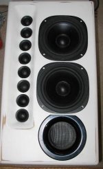
You could also choose a row of eight Dayton ND20: s power tapered or not, maybe in a wave guide similar to the new ‘presence speaker’ I just finish building for a friend of mine that is intended to be placed on each side between the mains and a center speaker:
http://www.diyaudio.com/forums/attachment.php?postid=1194269&stamp=1177625327&
Presence speaker: 1(5): precence.jpg and the wiring schematic for tapering 2(5): 8xtaper-ND20.jpg.
See picture 3(5): Peerless_SLS 830667.GIF
Who knows, my first comment using the aperiodic approach minimizes any possible internal wall reflexes via the stuffing and secures an alignment that acoustically doesn’t ring stand alone or when mating to a bass speaker in minimal boxes, but if you are using closed volumes below 3-4 L / driver you can expect ripple effects in the upper bass/lower midrange area that eventually masks any internal reflexes, so you must show a detailed drawing if you want a better answer based on your design.
Edgebc:
See pictures 4(5)-5(5) where dispersion plots of 7 6.5” drivers is shown as a consequence of inter driver c-c distances using the information given at:
http://www.diyaudio.com/forums/showthread.php?postid=1215500#post1215500
Opinions: Good array (2-way) performance can only be expected using the shown 2.71 ft array (or 12- 13 drivers for a 7 ft array) and a T line that is crossed over at 1 kHz 12 dB/octave or about 1.5 kHz 24 dB/octave.
b
1(5)
OK, I will probably not try the aperiodic venting anyway.
In my experience the aperiodic approach is the only way to keep the volume requirements for the M drivers at a manageable size, making the array as slim as possible, not too deep and without bad transient behavior as the high Qtc driver value otherwise will ensure in a too small box.
If running straight powering, is using one single volume for all 20 drivers still a very bad thing? Won't standing waves in the enclosure be a problem anyway, just at different frequencies depending on the size of the enclosures?
Installing a lot of drivers = 👎 in the same closed enclosure makes a multi freedom of n degree system and not a good idea for drivers with thin paper membranes especially in a closed box.
There will be interaction if the drivers are mechanically different i.e. if the fs and the suspension differs as they do within a batch of low cost drivers even if from the same production lot.
See the animated system freedom of two degrees coupled oscillators and try imagine what happens when 👎 drivers all slightly off specification is put in a long narrow box where also the acoustic load behind each driver is different but box position symmetric, hence the action from the many different ‘stretchy cords’ that must exist in a box with many drivers sharing the same volume:
http://www.kettering.edu/~drussell/Demos/coupled/coupled.html
more:
http://www.kettering.edu/~drussell/Demos/multi-dof/multi-dof.html
Bjorno, What is the main advantage of using a bessel array for the tweeters instead of just using one tweeter? The bessel array is meant to get a number of drivers to acoustically behave as one point source, right?
In my opinion a short Bessel array (5- 7 T-drivers) behaves as a good single point source if listening at 10(20(opt=minimum ripple)) x array-length = 10(20opt) x (4-6) x 1.5” = 5(10opt)-7.5(15opt) ft or beyond.
Phase issues (still holds the demand for flat FR) can be ignored and of minor importance if the Bessel array is crossed over above about 1.5- 2 kHz where the dispersion will be at least as wide for a single driver, horizontally or vertically.
Horizontal phantom MAA (minimum audible angle) is as for a single driver and experienced for the verticals too but if correspondingly 5-7-(8) drivers are configured in a straight array, the vertical MAA is wider but will be blameless to about 7-8 (>8) kHz if 1.5” drivers are used.
MAA? See:
http://www.diyaudio.com/forums/showthread.php?postid=1209527#post1209527
For a good design, choosing a crossover point here restricts the horizontal c-c distance between an M and T driver to < = 0.1 m* or about 4” if suppressed blameless horizontal secondary lobes of < = 12 dB is the minimum requirement as it should be in my opinion.
*Obviously this holds also for a single 4” T driver and a <= 4” M array drivers if minimum possible horizontal c-c distance is secured.
Then the horizontal azimuth coverage for a vertical oriented M-T array will be about + - 30 degrees at the – 3dB points if a second order LR filter is used.
The lobe levels, symmetrically at 60 degrees of axis would then be 12 db down at 3-4 kHz.
I think this is the very minimum limit to use when designing vertically oriented 2 way arrays considering minimum acceptable horizontal performance and will be surpassed if a 3” M and a 1.5” T driver is used.
For this case the secondary horizontal lobes at 3-4 kHz will be more than 18 dB down using the 12-dB/octave LR filter and I believe the resulting of axis coverage is wide enough and of high performance for an array.
However, I just suggested that you could start with a small row of Dayton ND20 T drivers, Bessel aligned or not = straight, until you can afford to buy more of them instead of one large T driver that later have to be removed leaving a hole with the wrong dimensions.
A larger 4” T-driver narrows the important horizontal dispersion and adding stronger secondary lobes due to larger horizontal c-c distance when compared to my rec. of using 1.5” T-drivers.
(The main drawback when using a single T driver to mate an M array at a certain listening distance is the vertical off axis mismatch that only improves if an adequate wave-guide or a T-driver with restricted vertical dispersion is in use.)
You could also choose a row of eight Dayton ND20: s power tapered or not, maybe in a wave guide similar to the new ‘presence speaker’ I just finish building for a friend of mine that is intended to be placed on each side between the mains and a center speaker:
http://www.diyaudio.com/forums/attachment.php?postid=1194269&stamp=1177625327&
Presence speaker: 1(5): precence.jpg and the wiring schematic for tapering 2(5): 8xtaper-ND20.jpg.
Does anyone have comments regarding my choice of driver for the bass uits? (sealed ~18l enclosure for an 8" Peerless SLS-213-830667)
See picture 3(5): Peerless_SLS 830667.GIF
Stuffing…I glued the last sides of the cabinets today. For dampening I have used a layer of "wavy" foam material (see pic) on the rear wall and one layer of 300g/m2 polyester wool in front of that. This leaves the backside of the front baffle and the front part of the side walls bare. Is this a bad thing?
Who knows, my first comment using the aperiodic approach minimizes any possible internal wall reflexes via the stuffing and secures an alignment that acoustically doesn’t ring stand alone or when mating to a bass speaker in minimal boxes, but if you are using closed volumes below 3-4 L / driver you can expect ripple effects in the upper bass/lower midrange area that eventually masks any internal reflexes, so you must show a detailed drawing if you want a better answer based on your design.
Edgebc:
…it is the wall-of-sound I want…I'm still not sure I understand why stacking 6 6.5 inch full-range Fostexs in a 7 foot sealed box is a bad idea…
See pictures 4(5)-5(5) where dispersion plots of 7 6.5” drivers is shown as a consequence of inter driver c-c distances using the information given at:
http://www.diyaudio.com/forums/showthread.php?postid=1215500#post1215500
Opinions: Good array (2-way) performance can only be expected using the shown 2.71 ft array (or 12- 13 drivers for a 7 ft array) and a T line that is crossed over at 1 kHz 12 dB/octave or about 1.5 kHz 24 dB/octave.
b
1(5)
Attachments
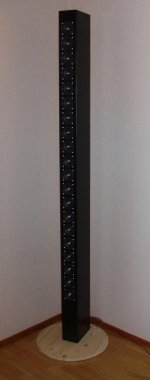
stage 1 finished
With all it's flaws, stage 1 is what I can call complete!
What surprises me is the stereo image and the detail of the sound. I am also positively surprised by both bass and treble extension.
I'm afraid I can't really hear any of the theoretical comb filtering which should take place from about 2500 Hz or something and up... Is there anything special to listen for?
Of course I will still try stage 2 and 3, a bass unit and either tweeter arrays or long band tweeters. Which one will be stage 2 and 3 respectively? I haven't decided...
Attachments
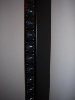
 that was quick
Your evaluation sounds interesting
How about some informative details of the final design ... drivers and how you have connected them, box design and what else 🙂
The drivers are 20 in each speker, 3" Aurasound NS3 194 8E. More info about them can be found here:
http://www.madisound.com/catalog/product_info.php?products_id=729
They seem to be sold out for the moment...
The sealed enclosures are made out of 12mm MDF board, glued and nailed together, and are 2000x110x200 mm on the outside, giving an internal volume of 30 l.
The holes for the drivers were cut with a "hole-saw" giving exactly the right hole diameter for the drivers!
The drivers are placed with an 83mm c-c distance.
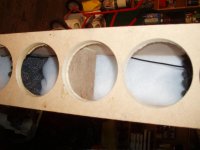
Despite all the good advice from people here, I did not part the enclosures into several smaller sealed units... There are dividing baffles though, (one between every two drivers) reaching a little past half way through the box. Every other sealed to the front baffle reaching back, and every other sealed to the rear baffle reaching towards the front baffle. (see the attached picture)
Some dampening material is placed against the rear baffle, both a wavy foam and a polyester wool.
In the end the enclosures were painted in semi-gloss black paint. Not very pretty I'm afraid. I sometimes overestimate my own skills in woodworking and painting...🙄
I wired the drivers "straight". groups of 5 drivers are wired in parallell giving four 1.6 Ohm groups, which are wired in series into a total of 6.4 Ohm.
As I said I am impressed by their sound! But after todays listening I do think they can be improved by eliminating the "comb filtering", even if I really can't point my finger at what sounds "wrong".
Feel free to comment any of my mistakes!
http://www.madisound.com/catalog/product_info.php?products_id=729
They seem to be sold out for the moment...
The sealed enclosures are made out of 12mm MDF board, glued and nailed together, and are 2000x110x200 mm on the outside, giving an internal volume of 30 l.
The holes for the drivers were cut with a "hole-saw" giving exactly the right hole diameter for the drivers!
The drivers are placed with an 83mm c-c distance.
Despite all the good advice from people here, I did not part the enclosures into several smaller sealed units... There are dividing baffles though, (one between every two drivers) reaching a little past half way through the box. Every other sealed to the front baffle reaching back, and every other sealed to the rear baffle reaching towards the front baffle. (see the attached picture)
Some dampening material is placed against the rear baffle, both a wavy foam and a polyester wool.
In the end the enclosures were painted in semi-gloss black paint. Not very pretty I'm afraid. I sometimes overestimate my own skills in woodworking and painting...🙄
I wired the drivers "straight". groups of 5 drivers are wired in parallell giving four 1.6 Ohm groups, which are wired in series into a total of 6.4 Ohm.
As I said I am impressed by their sound! But after todays listening I do think they can be improved by eliminating the "comb filtering", even if I really can't point my finger at what sounds "wrong".
Feel free to comment any of my mistakes!
Attachments
- Status
- Not open for further replies.
- Home
- Loudspeakers
- Multi-Way
- which loudspeaker design?