Not easy to tell. There are many candidates, with about same results: NJW0281/0302, NJW3281/1302, 2SC3284/2SA1303, 2SC3519/2SA1386.
50-70MHz@1-3A is posssible, with the actual output devices.I want to downsize or to eliminate the switching phenomen in the output stage.

To do this, you need to use the Lokanti output stage, or use Mosfets at the output - they do not have the phenomenon of "switching"I want to downsize or to eliminate the switching phenomen in the output stage.
The ones you can drive with fast enough drivers.If the driver can push through CBE and COB then you can use 4MHz output trz! You'll often see 200Mhz drivers in oldschool fast amplifiers.The switching on and off of a junction capacitance is the driver's job, the output trz drives an inductor .
Last edited:
Russian transistors VL035DN & VL035DP with Ft = 100MHz developed quite recently this year.Which is the fastest NPN/PNP pair power transistor for output stage ?
Attachments
Last edited:
Impressive data, really. Anyway, is it really ethical to source Russian devices, given the current situation?
Best regards!
Best regards!
Any device with a slew rate greater than 15V / microsecond is too fast for audio.
And audio tops out at 20 kHz or so.
So 100 Mhz Ft is also on the excess side.
Stick to what is easily available, and competent for the purpose.
As for the Russian situation, any comments will be political in nature.
But I remember reading a novel by an English author, a hijacked supertanker was used as a bargaining chip between Ukrainian and Russian sides.
So all that tells me is that it is a long standing conflict, I read the book in the 1980s.
And a wise man told me never to get involved in disputes between brothers, they know each other's secrets too well.
So let us stick to audio, and the availability of newly released parts from exotic sources will always be difficult.
The real problem is if you can do it in the first place.Impressive data, really. Anyway, is it really ethical to source Russian devices, given the current situation?
Best regards!
From my measurements 1386 3519 are the winners, but the others you quote are close. Good devices. No comment on 3284 1303 cause I did not test them.Not easy to tell. There are many candidates, with about same results: NJW0281/0302, NJW3281/1302, 2SC3284/2SA1303, 2SC3519/2SA1386.
You need drivers with high fT at the current they are used at. If your drivers idle at 25mA you need high fT at this current. Not at 1A like Mje15030.
Anyone know where to get these Russian transistors?
Who's stopping you from doing politics ?As for the Russian situation, any comments will be political in nature.
But I remember reading a novel by an English author, a hijacked supertanker was used as a bargaining chip between Ukrainian and Russian sides.
So all that tells me is that it is a long standing conflict, I read the book in the 1980s.
And a wise man told me never to get involved in disputes between brothers, they know each other's secrets too well.
So let us stick to audio, and the availability of newly released parts from exotic sources will always be difficult.
You can still buy in Russia. Ask the person if they sell transistors with shipping. And where can I buy more.Anyone know where to get these Russian transistors?
http://forum.vegalab.ru/showthread.php?t=92554
For your experiments with the output stage, it would be interesting to compare with other powerful transistors. And suddenly they will surpass the Japanese counterparts.
There is a comparison of MJW3281D+MJW1302D with VL035DN+VL035DP in terms of switching distortion.
http://forum.vegalab.ru/showthread.php?t=12016&page=53&p=3043881&viewfull=1#post3043881
Also, some people already use them in the output stages of the amplifier.
https://zen.yandex.ru/media/prophet...-202122-gg-vypuska-62f6236e324aad4233e6c02f?&
If I remember just older common Mosfets like IRFP140 , IRFP9140 get close to 240/260 Mhz
Far as I know for BJT Sanken has power devices in 60 to 80 Mhz range
Real trick is your driver stage transistors, so lower current demand of mosfet
allows smaller drivers in the 150 Mhz range
otherwise typical 30/40 watt BJT packages used as drivers only 30 Mhz
Far as I know for BJT Sanken has power devices in 60 to 80 Mhz range
Real trick is your driver stage transistors, so lower current demand of mosfet
allows smaller drivers in the 150 Mhz range
otherwise typical 30/40 watt BJT packages used as drivers only 30 Mhz
Good luck with charging and discharging them fast in linear circuits!If I remember just older common Mosfets like IRFP140 , IRFP9140 get close to 240/260 Mhz
Attachments
Well, a fast switching transistor will not help you with the"switching phenomen" or crossover distortion which I assume you really mean.
It's not a matter of the speed of the transistor. It's more a matter of what's driving the output stage and basic design principles.
There are some practice to lower the crossover distortion but all transistors that turns off will create switching distortion.
One way is to bias into class A operation. That will solve the problem but create other problems with your desire to downsize.
Lower value on the source resistor will help to lower higher order harmonics. 0,22 ohm instead of standard 0,33ohm?
Parallelling of output transistors will also lower the crossover distortion.
Many of my designs ends up with around 8 pairs parallelled if single ended or 32 pairs or more if a balanced design.
Error correction might help too.
I have done some tests and found it to be a dead end. Interesting idea but useless in normal amplifiers.
Better to bias into class A for a healthy part of the power capability before swithing over to class AB. 10 Watts can be enough in many cases.
Yes, I would like to try them. It would be nice to compare in an identical setup. I sent him a message.For your experiments with the output stage, it would be interesting to compare with other powerful transistors. And suddenly they will surpass the Japanese counterparts.
There is a comparison of MJW3281D+MJW1302D with VL035DN+VL035DP in terms of switching distortion.
http://forum.vegalab.ru/showthread.php?t=12016&page=53&p=3043881&viewfull=1#post3043881
The pictures by bukvarev in the thread you linked show problems at switching: there should be one spike per crossover, and his scope shows multiple spikes. This looks similar to what happens with inductive emitter resistors. Or perhaps it's the layout, as he says "the layout was the limiting factor". In any case, it's not really possible to draw conclusions about the transistors when this happens.
They will not be useful past 10MHz due to package inductance.If I remember just older common Mosfets like IRFP140 , IRFP9140 get close to 240/260 Mhz
That's a urban legend. If di/dt is below a certain value, there is no switching distortion. The critical di/dt value depends on the transistor. It's not all about fT, it's also about charge storage, which is not specified in datasheet. Using lower emitter resistor values and more bias reduces di/dt at switching, so it helps.all transistors that turns off will create switching distortion.
Nice.Yes, I would like to try them. It would be nice to compare in an identical setup. I sent him a message.
The pictures by bukvarev in the thread you linked show problems at switching: there should be one spike per crossover, and his scope shows multiple spikes. This looks similar to what happens with inductive emitter resistors. Or perhaps it's the layout, as he says "the layout was the limiting factor". In any case, it's not really possible to draw conclusions about the transistors when this happens.
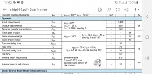
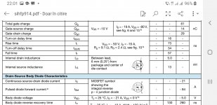
They will not be useful past 10MHz due to package inductance.
That's a urban legend. If di/dt is below a certain value, there is no switching distortion. The critical di/dt value depends on the transistor. It's not all about fT, it's also about charge storage, which is not specified in datasheet. Using lower emitter resistor values and more bias reduces di/dt at switching, so it helps.
What transistors suitable for an audio amplifier output stage have you found to have low enough di/dt to not create crossover distortion.
I'm curious because it would really be nice to get a low bias class AB output stage with no or little crossover distortion.
It's not all about fT, it's also about charge storage, which is not specified in datasheet.
Attachments
- Home
- Amplifiers
- Solid State
- Which is the fastest NPN/PNP pair power transistor for output stage?