A CCS is nothing but a power supply with a very high impedance.
Please DYaudiophyles do not imagine magic. There is none, but very high dynamic impedance. Better CCS is higher impedance.
The well known 2 BJT CCS is typically 10 MegOhm ( down to 1 volt ). Check at ESP Rod Elliott for details and clear explanations.
Please DYaudiophyles do not imagine magic. There is none, but very high dynamic impedance. Better CCS is higher impedance.
The well known 2 BJT CCS is typically 10 MegOhm ( down to 1 volt ). Check at ESP Rod Elliott for details and clear explanations.

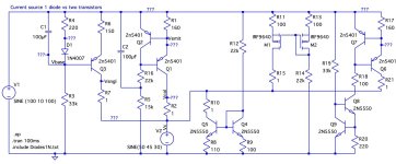
From ESP Rod Elliott the 2 Transistors CCS is:
1 MegOhm at 0.8 Volt
8 MegOhm at 2,5 Volt
Well. Far more than needed in most application.
1 MegOhm at 0.8 Volt
8 MegOhm at 2,5 Volt
Well. Far more than needed in most application.
OP issue
Using feedback CCS was good idea, likely current was set to high.
The actual problem is the rest of the amp.
Bias was likely difficult to set or had no range since current was too high.
The bias will dance regardless because of the design
Using feedback CCS was good idea, likely current was set to high.
The actual problem is the rest of the amp.
Bias was likely difficult to set or had no range since current was too high.
The bias will dance regardless because of the design
I don't really understand this, but perhaps because I'm not referencing the circuit correctly..The PSRR of a simple zener plus resistor current source is quite high
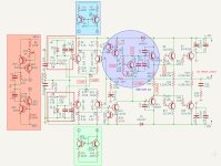
From the pic in post 18, there's a 15V zener stabilised circuit above ground, which feeds via a 22k resistor to the lower LTP, sitting on -28V. So the +28V rail is isolated - but when the -28V rail starts flapping about (for whatever reason), doesn't that effect the LTP ?
A CCS of 2 BJTs would be sitting at +28V, but providing a constant current whatever the rails do (subject to speed, the zener is faster of course). But maybe the constant current has issues as the LTP is sitting the -ve rail, so that's following the -28V anyway.. ?
Perhaps the answer is that the LPTs should also be standing on the stabilised zener points? So the LTPs both see a stable +15 / -15V supply, and are therefore isolated from the main rail, both of which will be bouncing around with the music anyway.
One of the main factors that affects Zener regulation when fed from a current limiting resistor is the dynamic impedance of the Zener. But, if the zener is heavily decoupled (as I did in the e-Amp), the dynamic impedance drops and the equivalent CCS output impedance goes up.
In concept I prefer the zener where possible, as it's very very fast.Zener regulation
The CCS is in my view a purer constant current, but the transistors take time to react.
Either is plenty fast for audio - this isn't an RF amplifier we're talking about! My immediate comment is that the limiting factor for linearity seems to be that the long-tailed pairs have resistors as loads, rather than current mirrors, so will likely have a lot more even-order distortion than they could have - I believe this might be a larger problem than the long-tailed pair sourcing - it would be interesting to simulate.
Collector- base capacitance (and to a lesser extent collector-emitter) limits the output impedance at high frequency. Which is why you still want to use a good VAS transistor to load the VAS, and a small signal device for the LTP’s tail. No TIPs. Use the appropriate transistor, and it generally pushes the effects out of band.
Tried and failed to find Bonsai's article so I'm not sure exactly what he tested. In any case, it matters that the CCS transistor has a capacitor decoupling at the base, both for noise and HF impedance.The PSRR of a simple zener plus resistor current source is quite high and in a practical application as good as a two transistor or diode-transistor CCS, and it is very wide band. I show the sim results in me e-Amp write-up on my website.
View attachment 1387038
Could you draw this out please? There are two transistors, and I was under the impression that the transistors had to be free to 'move', to correct for voltage variations affecting the current.it matters that the CCS transistor has a capacitor decoupling at the base, both for noise and HF impedance.
Hmm, yes and no 🙂Either is plenty fast for audio - this isn't an RF amplifier we're talking about!
We probably only listen to 15-20kHz tops, ultrasonics can perhaps be heard as beats etc.. but that's all fine in a zero feedback amplifier.
But when we close the GNFB loop the loop response time, and the temporal accuracy of the push transistor vs the pull transistor matters. This, at least is what my hours of simulation of various toplogies on the Maplin MOSFET amplifier, and a push-pull tube amplifier with primary side NFB loops revealed.
The stability was affected by adding CCSs everywhere they might be useful - and I think there were two reasons:
1. The open loop gain would increase
2. The response time of the loop would go down.
With a resistor, it's not the best for an LTP tail, or a VAS transistor tail, but it's very fast, and if fed from a stabilised rail it's a pretty solid idea. The CCS improves linearity of many devices so I like them, but it does take some time to react - at least it did in the simulator - which restricted the amount of GNFB or NFB I was able to apply, before the phase margin started ringing stuff.
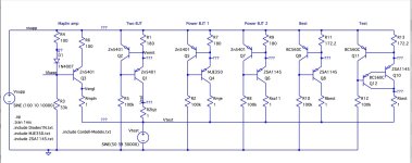
In the simulator one can simply feed a voltage waveform into a CCS and plot the current, each has it's own frequency response. Actually I may have some of the netlists still.. I'll look.. - aha - attached 🙂
The same even with an LTP phase splitter - one side has a slight delay over the other, as the 2nd transistor has to react and move, with it's various parasitics slowing it down.
So I found I had to be quite careful with the 'speed' to get a GNFB circuit to react fast enough for my purposes (which of course may not be the same goals for others!).
Attachments
- Home
- Amplifiers
- Solid State
- Which is better for CCS, a Zener Regulator or a Long Tail Pair?