Late but not too late, I got *Almost* all these bugs out of the Circuit.. and there were quite some bad ones involved which kept me from Assembling the board from that last post of mine..
This morning I tested that Amplifier one more time, just to make sure nothing changed and found a Solution for this Problem Check out the Pictures.
These Pictures I place here are from 2 weeks ago..
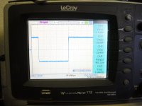
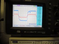
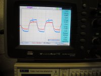
The pictures are showing the unwanted distortion, @50Khz and 100Khz
This has been fixed in the meantime even, it's out of the hearable range.. Still it has influence on the signal below.
Now, taking a chance that I have to create a new board one more time it's worth it..
Let you know soon. just this much all other numbers are good, and the listening to that amp is a pleasure.
Picture 1KHz is taken with the signal driven into 8Ohms dummy load
Picture 50Khz and 100Khz are driven into 2Ohms Dummy Load. Start of Distortion
Picture 913Hertz Sine Wave is driven into 4Ohms Dummy load. Short before Clipping
Exact RMS voltage can be read in the pictures.
So this makes an linearity starting @10 Hertz to 100K with a distortion not more than 0.5% all over the bandwidth.
When the real Amp is assembled I will make another read out also with REW as the distortion meters.
To find out exactly how far up the amp is functional.. under what load.
I use the prototype on 2 Ohms and it proves itself already..
Final Circuit including PID control I will place in PDF when the amp has finished.. also layout..
This morning I tested that Amplifier one more time, just to make sure nothing changed and found a Solution for this Problem Check out the Pictures.
These Pictures I place here are from 2 weeks ago..
The pictures are showing the unwanted distortion, @50Khz and 100Khz
This has been fixed in the meantime even, it's out of the hearable range.. Still it has influence on the signal below.
Now, taking a chance that I have to create a new board one more time it's worth it..
Let you know soon. just this much all other numbers are good, and the listening to that amp is a pleasure.
Picture 1KHz is taken with the signal driven into 8Ohms dummy load
Picture 50Khz and 100Khz are driven into 2Ohms Dummy Load. Start of Distortion
Picture 913Hertz Sine Wave is driven into 4Ohms Dummy load. Short before Clipping
Exact RMS voltage can be read in the pictures.
So this makes an linearity starting @10 Hertz to 100K with a distortion not more than 0.5% all over the bandwidth.
When the real Amp is assembled I will make another read out also with REW as the distortion meters.
To find out exactly how far up the amp is functional.. under what load.
I use the prototype on 2 Ohms and it proves itself already..
Final Circuit including PID control I will place in PDF when the amp has finished.. also layout..
Attachments

Last edited:
Hi Guys
Hope everyone enjoys Holidays better than me, Home alone..
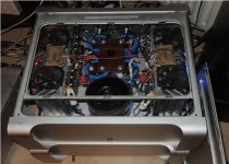
If you read recently of my Bad Luck that I burned a Transformer, or at least the fuse of it of a Class A Current source amplifier which I build back in 2017, then this here is about that amplifier.
So I repaired that Toroid be unwinding a few round of the outer Coil and remove the Fuse, got a new one after rewinding it in the top layer but with a deeper Temperature where it has to cut off..
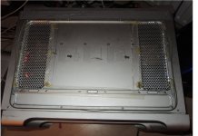
Since I'm absolutely not happy that this could happen again, I modified the top cover of the amp and Cut out two Air vent slots.
Of course, just cutting out these slots would be ugly so I cover them with some Cover I made by hand..
Check out the pictures..
All the slots and the inserts have been made with a small Table Saw, a Jig Saw, a piece of wood and some sanding paper, and a plastic hammer.. Is not there to win a price, but there to have better cooling.
Guys if we will not see us in the near future, which everyone a Happy 2022 as soon it's arrives..
I will be back sometime in the next year as soon my newest Class A, Variable Bias Current amplifier has been finished.
Thanks for reading.
Chris Hess
Hope everyone enjoys Holidays better than me, Home alone..
If you read recently of my Bad Luck that I burned a Transformer, or at least the fuse of it of a Class A Current source amplifier which I build back in 2017, then this here is about that amplifier.
So I repaired that Toroid be unwinding a few round of the outer Coil and remove the Fuse, got a new one after rewinding it in the top layer but with a deeper Temperature where it has to cut off..
Since I'm absolutely not happy that this could happen again, I modified the top cover of the amp and Cut out two Air vent slots.
Of course, just cutting out these slots would be ugly so I cover them with some Cover I made by hand..
Check out the pictures..
All the slots and the inserts have been made with a small Table Saw, a Jig Saw, a piece of wood and some sanding paper, and a plastic hammer.. Is not there to win a price, but there to have better cooling.
Guys if we will not see us in the near future, which everyone a Happy 2022 as soon it's arrives..
I will be back sometime in the next year as soon my newest Class A, Variable Bias Current amplifier has been finished.
Thanks for reading.
Chris Hess