I'm wanting to build a simple supply for a op-amp circuit using the LM7812/7912 regulators, but I'm not sure what size and what type of electrolytic capacitor to use at their outputs.
I read in another thread that low ESR caps like I normally use(Panasonic FM, FR) are not recommended because of rising impedance with the LM regulators under a light load.
Also, I see people using anything from 47uF up to 470uF on their outputs.
So what is the preferred series of caps to use and what size should it be?
Is it a good idea to use .1uF film caps after these electrolytics?
Thanks...
Given the inductive output impedance of most regulators it is best not to stray too far from the datasheet recommendations unless you really know what you are doing. In essence, you can choose where (i.e. at what frequency) you want to place the peak in output impedance and noise from your regulator.
What does the datasheet suggest?
The datasheet shows a whopping 1uF. Sounds too small to me, but I'm no engineer.
Perhaps someone who have used these extensively can comment.
Attachments

The datasheet shows a whopping 1uF. Sounds too small to me
That's only for a tantalum type; most now use a 10uF electrolytic.
These are for regulator stability, not filtering.
Last edited:
1uF tantalum is ideal but a 1uF decent electrolytic is fine. Any more capacitance and the regulator will not function properly, any less and the regulator may take off and oscillate.
The datasheet shows a whopping 1uF. Sounds too small to me, but I'm no engineer.
Perhaps someone who have used these extensively can comment.
78xx can be used without a output capacitor, but a 1uf tantalum
improves stability , 79xx use 1uf tantulum
Okay, I thought these capacitors were for additional filtering. Stability never crossed my mind. Shows just how much I know, huh?😱
Which is preferred, or does it matter, a 1-10uF tantalum or electro?
Which is preferred, or does it matter, a 1-10uF tantalum or electro?
Hi
There were/are concerns about the unsound mining of tantalum
exploiting those involved, as well as environmental impacts
https://en.wikipedia.org/wiki/Coltan_mining_and_ethics
If you are replacing with electro types datasheet suggests 25uf
With a bit of time you could design a capacitance multiplier circuit
for each polarity, on the regulators outputs, and use far lower values
or gain advantage of a cap multipliers ability of providing
typically 200x the used capacitance value. The figure of merit
being the transistors hfe figure.
My commercial Italian amp has it. It uses 47uf Electrolitic + 0.1uF Polyester cap after the regs.
Last edited:
Thanks Chris. I've heard of cap multipliers before, but have no clue about designing/building such a supply.
Just curious...if these caps are for stability purposes, why would you want to multiply the capacitance by a figure of 200 times?
Just curious...if these caps are for stability purposes, why would you want to multiply the capacitance by a figure of 200 times?
if these caps are for stability purposes, why would you want to multiply the capacitance by a figure of 200 times?
A capacitance multiplier would not be appropriate to replace the regulator's output capacitor to ground.
Certainly, you could use one after the output capacitor.
The regulator's output capacitor only needs to be large enough to ensure the regulator's stability.
Larger than that slows down the regulator's transient response unnecessarily.
Last edited:
The regulator's output capacitor only needs to be large enough to ensure the regulator's stability.
Larger than that slows down the regulator's transient response unnecessarily.
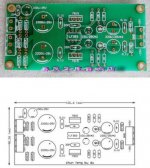
Looking at this 7815/7915 board on eBay, it uses a LF353 op amp. What does the op amp do?
The board uses 10uF caps like you suggested, but I also see 220uF caps near the outputs.
So the large 220uF caps will slow down the regulators' transient response?
Attachments
What does the op amp do? the large 220uF caps will slow down the regulators' transient response?
It's difficult to tell what the actual circuit is. The op amp power pins do seem to run off the regulator outputs.
Do you have a schematic?
Last edited:
No, the seller doesn't provide a schematic:
Regulator Power Supply Board LF353 L7815 L7915 Dual AC 12V 15V Finished Board | eBay
I see pin 5 is grounded. I just wondered what the op amp brings to the table to improve performance.
Still, you don't recommend those 220uf caps?
Regulator Power Supply Board LF353 L7815 L7915 Dual AC 12V 15V Finished Board | eBay
I see pin 5 is grounded. I just wondered what the op amp brings to the table to improve performance.
Still, you don't recommend those 220uf caps?
It's difficult to tell what the actual circuit is. The op amp power pins do seem to run off the regulator outputs.
Do you have a schematic?
The values of capacitance suggested already, ensure the regulator
remains stable. You should build one of Walt Jungs regulators.
they will teach you far more about actual requirements placed
on regulators.
A usual op amp based regulator will have some reference voltage
with which it compares the incoming voltage to, then providing usually a replica
of that reference. Compare the board you have found to the components
used here: References & Regulators | Walt's Blog 2014
My conclusion is the op amp does nothing, other than possibly adding noise.
Cheers / Chris
Last edited:
Hi Chris,
I looked over Walt's Blog before you posted. I believe I got the same link after looking at the "Super Regulator" board offered by the DIY Store.
The store photo shows DIP-8 op amps, while the actual board seems to use SOIC-8 op amps.
Jan Didden also has a "simple" shunt regulator design in another thread. Looks as though he's not selling(or taking orders) for any more boards, so I PM him asking for the layout file or Gerbers so I can purchase a few boards for myself.
Would a shunt supply offer audibly better performance than a LM-based supply?
Hi Chris,
I looked over Walt's Blog before you posted. I believe I got the same link after looking at the "Super Regulator" board offered by the DIY Store.
The store photo shows DIP-8 op amps, while the actual board seems to use SOIC-8 op amps.
Jan Didden also has a "simple" shunt regulator design in another thread. Looks as though he's not selling(or taking orders) for any more boards, so I PM him asking for the layout file or Gerbers so I can purchase a few boards for myself.
Would a shunt supply offer audibly better performance than a LM-based supply?
You are on the right path, yes a shunt supply will be audibly much better,
Something which is usually not addressed in more exotic designs is short circuit protection. They design for go, but not stop. A fuse or circuit breaker though
remains essential to use with all power supplies.
Cheers / Chris
- Status
- Not open for further replies.
- Home
- Amplifiers
- Power Supplies
- Which Capacitors After LM78xx/LM79xx?