Here's the one I'm using:
A lot of people here helped me with the circuit design.
I think removing the .047uF cap is the only change I've made.
Glenn
A lot of people here helped me with the circuit design.
I think removing the .047uF cap is the only change I've made.
Glenn
Here's the one I'm using:
A lot of people here helped me with the circuit design.
I think removing the .047uF cap is the only change I've made.
Glenn
Hi Glenn,
I am planning on building this preamp, what is the diode for on the connected to the grid of the second triode?
How many ma across per tube (two triodes)?
Thanks.
Hi Alex-
Read post #28 by Sy:
http://www.diyaudio.com/forums/tubes-valves/66260-12ay7-6sn7-preamp-psu-check-3.html
Current draw is the 5.6mA on the schematic (per tube).
The thread I posted above has all the questions I asked about the power supply for this preamp. It's been a while since I built this, so I don't remember what I wound-up with for total current draw from the PS.
Good luck
Glenn
I found the PS schematic.
Note that the rest of the schematic is not current, so use the schematic in the previous post!!
Note that the rest of the schematic is not current, so use the schematic in the previous post!!
An externally hosted image should be here but it was not working when we last tested it.
You know, I should mention that this is not really a preamp. I think it has unity gain. The reason I use this is to give my CD's that tube sound.
I just thought I should clarify this.
I just thought I should clarify this.
You know, I should mention that this is not really a preamp. I think it has unity gain.
Trying to figure out why it is a unity gain config.
Common cathode followed by CF no?
Won't there be an amplification of ~20?
Please correct me if I'm wrong or not understanding something here.🙁
If this provides no gain then maybe a better option to a CF between my cdp and ss power amp for that tube warmth.
hi guys,
I want to try this preamp (6sn7 version).
Can anyone suggest a schem for the PSU section?
I would go with a SS rectifier
V.
Use the Salas high voltage shunt regulator

http://www.diyaudio.com/forums/power-supplies/134801-simplistic-mosfet-hv-shunt-regs-115.html post #1150
Trying to figure out why it is a unity gain config.
Common cathode followed by CF no?
Won't there be an amplification of ~20?
Yes, it is. And no, more like about 10.
A well-designed cathode follower will NOT add warmth; it won't add anything. A poorly designed one could possibly give you excess 2nd harmonic distortion which you might perceive as warmth.
I am planning on building this preamp, what is the diode for on the connected to the grid of the second triode?
It's a polarity protect diode that keeps the control grid from going positive during power up. It shouldn't really be necessary since 6SN7GTBs were designed for operation in Class *2, and the control grids were hardened and equipped with radiator "wings".
You could also avoid the diode by separating heater from DC power. Power up the heaters before turning on the HV DC, and positive grid voltage won't be a problem.
Otherwise, the diode adds a non-linear, voltage variable capacitance to Cgk. Not having nasty, non-linear, voltage variable capacitances is one of the advantages that hollow state has over solid state.
Hello im mew, im from Argentina. Some one has used a 6cg7 for this circuit? Im looking for a preamp or booster using the 6cg7 to put between the acustic guitar and a solid state amp.
6CG7 will work as an exact functional replacement for the 6SN7 in preamp applications.
Last edited:
I can recommend the SRPP, DIY ECC802S (12AU7 / ECC82) Vacuum Tube SRPP Preamplifier
Built a couple versions of this preamp. Simple and sounds great. Hardwired...and I use 5814 tubes. 7812 in the heater curcuit.
Built a couple versions of this preamp. Simple and sounds great. Hardwired...and I use 5814 tubes. 7812 in the heater curcuit.
Thanks! I'll search for a 6SN7 preamp circuit.
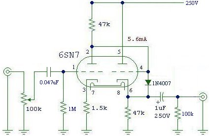
I've built the following circuit, and many variations thereof, many times over the last ten years or so. It's a very adaptable and clean circuit, with less distortion than the SRPP circuit. If you will use it with multiple sources, leave the input capacitor in to block DC from the input tube grid. It's very easy to build, and if you use a decent power supply you will be very pleased 🙂
Here's the one I'm using:
A lot of people here helped me with the circuit design.
I think removing the .047uF cap is the only change I've made.
Glenn
The 6CG7 will work perfectly in it, and will require no parts changes. Gain should be ~10 or so. The diode isn't strictly necessary, but wont hurt a thing or effect sound quality in any way. It protects the grid during power-up and then reverse biases itself out of the circuit.
Last edited:
Around 400~600 ohms, if I remember correctly, probably closer to 500~ or so. Should be happy swinging a dozen volts into a 10K~47K load. If you need lower output impedance build it with a 6DJ8 on the cathode follower.
I had John Hogan 6SN7 pre and to this day still think it was the best I've heard. I have the schematic somewhere. I'll post it tomorrow.
> Between pin 2 and 4 mess a coulping cap?
No.
Pin 2 probably sits around 125V. Pin 4 "wants" about a 125V bias to be happy, to get significant voltage and current in its cathode resistor. We could block V1's plate voltage, then re-establish bias for V2, and sometimes that is best. But this way works, and is *simple*.
No.
Pin 2 probably sits around 125V. Pin 4 "wants" about a 125V bias to be happy, to get significant voltage and current in its cathode resistor. We could block V1's plate voltage, then re-establish bias for V2, and sometimes that is best. But this way works, and is *simple*.
its is a direct coupled design...no need for coupling cap between pins 2 and 4.....
instead of the 1n4007, i use a neon NE-2 lamp...
instead of the 1n4007, i use a neon NE-2 lamp...
- Home
- Amplifiers
- Tubes / Valves
- Which 6SN7 preamp should I build?