If you're sourcing your Naim clone's from China they'll take several weeks to arrive, PSU components you should be able to source locally.
Bridge rectifier (I've read discrete diodes are better but rectifiers are a lot easier to use!)
GBPC3506 - FAIRCHILD SEMICONDUCTOR - BRIDGE RECTIFIER, 35A, 600V, GBPC | Farnell United Kingdom
Caps I'd suggest at least 10000 uF x 63V but I need to have a look at what's currently available, more later!
25A or 35A 200V or 400V or 600V bridge rectifier.
Post18 shows the Main Audio Ground (MAG) soldered onto the wire connecting the smoothing capacitors.
DO NOT copy this.
Locate the MAG near the power amplifiers and the Speaker Terminals. Bring single wire connections from all the various parts of the circuit to this MAG. Bring the PSU Zero Volts to the MAG.
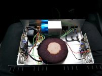
You sure? with a dual rail PS you need to ground the other cap terminals as in the image below, the wire connecting the caps is connected to a central chassis ground (via the green wire). Possibly not an ideal "star" earthing arrangement I'll admit but that amp has been happily playing for over 20 years with no noise or hum 🙂

That is precisely how not to do it, yet it is quite popular.
Always keep charging currents well away from the ground. The signal ground should always be connected to the output (clean end) of the PSU, not the rectifier (dirty) end.
Always keep charging currents well away from the ground. The signal ground should always be connected to the output (clean end) of the PSU, not the rectifier (dirty) end.
As a hobbyist I'm always open to suggestions, is the issue here connecting the various grounds (speaker, transformer ground etc) to wire link between the caps and then to chassis ground?
Should everything (transformer ground included) go to the chassis ground and then to the cap ground, -ve speaker terminal, input signal ground?
A schematic showing the correct grounding approach would be greatly appreciated.
Should everything (transformer ground included) go to the chassis ground and then to the cap ground, -ve speaker terminal, input signal ground?
A schematic showing the correct grounding approach would be greatly appreciated.
If you're sourcing your Naim clone's from China they'll take several weeks to arrive, PSU components you should be able to source locally.
Bridge rectifier (I've read discrete diodes are better but rectifiers are a lot easier to use!)
GBPC3506 - FAIRCHILD SEMICONDUCTOR - BRIDGE RECTIFIER, 35A, 600V, GBPC | Farnell United Kingdom
Caps I'd suggest at least 10000 uF x 63V but I need to have a look at what's currently available, more later!
The caps I used in the Crimson amps are from RS and look to be still available, I selected them for long term reliability more than anything else, 20 years on they still work 🙂
Buy Aluminium Capacitors Al electrolytic screw cap,15000uF 63V Kemet ALS30A153KE063 online from RS for next day delivery.
Bear in mind electrolytic caps do have a limited lifespan so will need to be replaced every 10 - 20 years (depending on usage, brand, operating temperature etc.)
I'm sure there's plenty of threads on caps in the forum so have a look for what brand are popular, although audiophile grades will be pricy.
The CHASSIS connection is for SAFETY ONLY.
The audio grounding has no reason to connect to Chassis.
Temporarily build up the amplifier with a MAG located correctly. Get it working with no noise/hum.
Install the whole lot in the Chassis. Permanetly connect Chassis to PE.
Now you can connect some part of the MAG, or any stout wire connected to that MAG, to Chassis, anywhere on the Chassis. It does NOT have to go back to the PE bolt.
The reason for the "stout" wire is that if there is catastrophic failure on the mains connections that somehow shorts to any of the amplifier parts, then that Stout wire has to pass Fault Current back to your mains socket. That Fault Current must be high enough to rupture the Mains Fuse as fast as is possible. It might be 1us, or 1ms, 1s. What you DON'T want is it taking 1minute, giving you long enough to get up out your seat and go and touch your now faulty amp because it went silent, before the mains fuse has blown and the arc extinguished.
Last edited:
I agree.That is precisely how not to do it, yet it is quite popular.
Always keep charging currents well away from the ground. The signal ground should always be connected to the output (clean end) of the PSU, not the rectifier (dirty) end.
That diagram is quite simply wrong in some respects and completely misleading other important respects.
The Earth symbol is wrong.
That Earth symbol should be a Chassis symbol. They are different.
Is the fuse on the Neutral?
Last edited:
I'm sure a little searching will find something useful. This same question comes up month after month, as people keep making the same mistakes and then wondering where the hum/buzz came from. Strangely, some of us keep giving the same answers - this is because they are the right answers and actually work.Ceekay said:A schematic showing the correct grounding approach would be greatly appreciated.
It comes down to the FACT that many Members will not do the research that their project and their lives deserves.
So many just want to rush and end up with a botch job that can be dangerous.
So many just want to rush and end up with a botch job that can be dangerous.
I'm not 100% sure about this, but "The Art..." is not for an absolute beginner. my formal training (computer engineering) includes analog which goes a bit beyond the basic stuff so my perspective is different. I don't have problems understanding it but I'd have a hard time believing an absolute beginner can deal with it. maybe I'm wrong but some of the Amazon reviews confirm it and it's worth noting that some of the reviewers come from a physics background.The usual advice is to buy 'The Art of Electronics' by Horowitz and Hill. Read it.
but with a tiny bit of effort it's worthwhile, the first 2 chapters get you pretty far without the tedious math some other books contain (which would turn off 9 out of 10 people).
FWIW, I hear the 3rd edition is due some time this year.
Last edited:
Maybe. It would depend on how much elementary science the reader had.mr_push_pull said:I'm not 100% sure about this, but "The Art..." is not for an absolute beginner.
I started at about age 13 by reading Practical Wireless magazine. A few years later I read 'Foundations of Wireless'. I'm not sure how well known that is outside the UK. Someone starting as an adult would hopefully be starting from a better base as they would know more science and maths than an early teenager.
I think your proberbly right, While I am not a hardcore DIYAudio Enthusiast i would like to give the basics a good go.It comes down to the FACT that many Members will not do the research that their project and their lives deserves.
So many just want to rush and end up with a botch job that can be dangerous.
I wouldn't like to nor am I deeply involved enough to spend 2-3 years learning only the basics, and another decade or so to be come advanced before I start my Build project.
I do understand the basics of electrics so i am fully aware of saftey and I have modified a few amplifiers in the past.
I work with Electonic speed controllers very offen, but generally jsut replacing parts i have never worked from schematics before and I think thats my biggest pitfall.
I think I am way in over my head here, Its something I would feel comfortable doing with some fairly strong guidence but I feel I maybe upsetting some of the more hardcore enthusiasts asking so.
I was hoping for a simple guideline to connect it all up and I'll solder everything together using pre-built boards.
Craig
As I said, if you need 'strong guidance' then you need a well-documented kit (or a local enthusiast with plenty of time). It is very difficult to remotely talk someone through a procedure which he doesn't understand. Experience shows that what often happens is that he doesn't do what he thinks he has done (and tells us he has done). Then in trying to remotely debug the faulty circuit he may measure something different from what we tell him to measure. Apart from the frustration (on both sides) there are safety issues.
We can't tell you "connect the red wire to terminal X and the blue wire to terminal Y", because we don't know what colour scheme you used or what your terminals are called - except in a kit they won't be labelled anyway. That is why we work from circuit diagrams. The diagram describes most of the circuit - the missing part is parasitics but that is the part which catches people out. We can help someone who can read a circuit, because we have a common mode of communication. We can say 'measure the voltage at the anode of V3' - and he goes and does it and reports back to us. Doesn't work if he doesn't know what an anode is, or which valve is V3.
I realise that you probably think we are being awkward. It is not a matter of 'upsetting' people, but experience of helping newbies. How would you explain (remotely) to someone how to cook a complicated meal if they couldn't read a recipe and didn't know what the ingredients were (and looked like)? The expert says 'peel a potato' - the newbie asks 'what is a potato? what is peeling? Oops, I just sliced a lump off my finger.' - you get the picture?
The fact you are aware of your limitations is a start.
That makes you take CARE.
Read and re-read instructions. If you are still not sure then ask again using a different form of the words.
We will try to get you through safely.
But, I go back to some advice I have offerered more than once.
A beginner that does not yet understand what the circuit does, must start with a well documented build that has been thoroughly tested.
If you never LEARN how the electricity & circuit works then you can never progress beyond COPYING exactly an existing well documented and tested project.
Thanks for the wise words.
I think I may have been a little ambitious to do this project - While I do have a basic understanding its not as much as I first through, (i do know what an anode is though haha).
I was thinking I could basically take a Toroid transformer, connect for EG 28V+ to the ac + in on the bridge rectifier and then connect DC + out from the rectifier to the Cap and then to the Amp board.
I have stupidly talked myself into something I thought would be a moderate project which turned out to be considerably more difficult than I would have hoped.
Really sorry to waste all your time guys.
I got this amp for nout sounds great any idea's what make it is
Attachments
Last edited:
- Status
- Not open for further replies.
- Home
- Design & Build
- Parts
- Where to start?