Hey guys,
So I am new here and new to DIYaudio in general but I have dabbled a little bit in electronics but not too much.
Unfortunatley I have killed my Quantum amp and decided i fancied building a pair of these NAP-140 Clones from eBay.
Now the question is where do I start?
I understand I am going to need a Torodial transformer and a bridge rectifer however I am at a bit of a loss because while I understand the transformer froms voltage as required and supplys current I am not entirely sure how or what the bridge rectifier is/for or how to wire it.
So If I buy these kits, what else would I need?
EDIT:
As for the casing, I have a CNC machine so i was thinking of a nice solid aluminium case with Naim engraved on the front.
Thanks
Craig
Last edited:
It might be best to find out. Plenty of information on the web or in books. Either buy a packaged (or kit) power supply, or learn how to design and build what you need. Mains PSUs can be dangerous so don't go beyond your own understanding.I am not entirely sure how or what the bridge rectifier is/for or how to wire it.
Thanks for that
I am a quick learner and very confident with things like this, I could do with a boost start to gst the ball rolling, any tips on a good place to look?
I am a quick learner and very confident with things like this, I could do with a boost start to gst the ball rolling, any tips on a good place to look?
Try this link there's an excellent section on solid state power supplies
DIY: solid state
Edit just remembered Avondale audio and as DF96 says treat the PSU's with respect, afterall 100W amps run at around +/- 50V DC i.e. 100V across the power rails you will feel that!
http://avondaleaudio.com/
DIY: solid state
Edit just remembered Avondale audio and as DF96 says treat the PSU's with respect, afterall 100W amps run at around +/- 50V DC i.e. 100V across the power rails you will feel that!
http://avondaleaudio.com/
Last edited:
Try this link there's an excellent section on solid state power supplies
DIY: solid state
Edit just remembered Avondale audio and as DF96 says treat the PSU's with respect, afterall 100W amps run at around +/- 50V DC i.e. 100V across the power rails you will feel that!
http://avondaleaudio.com/
Thanks for that,
While I feel confident at Soldering, Wiring etc (I have done it with Electronic speed controllers, Lithium batteires etc) I am not very good at reading schematics.
I really want to try this myself but is there anywhere I can look at a more basic wiring Diagram?
For E.g.
Transformer -> Resistor -> Rectifier -> amp
It would help me out greatly and is much appreciated.
I really hope I can put something together,
You must learn to read circuit diagrams. Then your confidence will have a solid foundation.
The usual advice is to buy 'The Art of Electronics' by Horowitz and Hill. Read it. Audio electronics is like every other worthwhile pursuit: you need to do some work at the start to get you going, then you can start doing the enjoyable stuff.
The only alternative is to buy a kit with detailed instructions, and then follow them precisely.
You must learn to read circuit diagrams. Then your confidence will have a solid foundation.
The usual advice is to buy 'The Art of Electronics' by Horowitz and Hill. Read it. Audio electronics is like every other worthwhile pursuit: you need to do some work at the start to get you going, then you can start doing the enjoyable stuff.
The only alternative is to buy a kit with detailed instructions, and then follow them precisely.
I guess the later is more what I am looking for with the exception I would prefer to select my own parts.
Is there a general rule of thumb with wiring power supplies?
I mean in most electronics its + to + and - to - but I need to use Bridge recitifiers and Caps.
On what basis are you going to select parts: fashion or understanding? Much better to trust the kit supplier. You can always 'upgrade' later.I would prefer to select my own parts.
Yes. Always follow the circuit diagram, and make sure you get the grounding right (which might not always be shown explicitly in the diagram).Is there a general rule of thumb with wiring power supplies?
So you need to know what they are and what they do, or simply follow detailed instructions in a kit.I mean in most electronics its + to + and - to - but I need to use Bridge recitifiers and Caps.
Thanks again, I have been looking at power supply kits from the same seller, maybe thats the way forward and a good way to learn.
You can always do some reading in parallel with building the kit. The aim is that you then don't have to blindly follow instructions. Instead you still follow the instructions, but with some understanding. That is the way to learn. Or a way to learn.
Don't expect to learn electronics in a few weeks. A couple of years will get you started!
Don't expect to learn electronics in a few weeks. A couple of years will get you started!
Thanks guys, After deciding to go with some pre-built modules.
Would these be compatible together?
2pcs Classic NAP 140 CLONE mono power amplifier board | eBay
Then:
6*10000uF/80V high quality power supply board for amp | eBay
Finally
300W 220V Toroid Transformer for audio Out:2X40V+2X15V | eBay
I wouldn't be missing anything then other than the switch?
Would these be compatible together?
2pcs Classic NAP 140 CLONE mono power amplifier board | eBay
Then:
6*10000uF/80V high quality power supply board for amp | eBay
Finally
300W 220V Toroid Transformer for audio Out:2X40V+2X15V | eBay
I wouldn't be missing anything then other than the switch?
Is your Quantum, the company that offshoot from Crimson Elektric?
Crimson is still producing and Brian Powell is a Member here.
He may be able to do something by way of help getting your Quantum running again.
Crimson is still producing and Brian Powell is a Member here.
He may be able to do something by way of help getting your Quantum running again.
I noticed you had been using Quantum amps (compact pre power set?), if I remember correctly they were a prebuilt offshoot of Crimson Elektrik kit amps.
The original Crimson designer/owner is active on the forum try PMing
bepowell about repairing/upgrading your Quantum amps.
I built several Crimson Elektrik amps over 20 years ago and although I don't use one currently I've been modding one for my nephew.
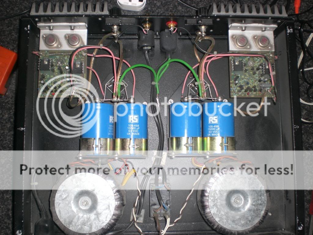
This one was constructed as full dual mono, that is a transformer (300VA), rectifier (25A 400V) and capacitor (15000uF) assembly for each channel.
I noticed you had been using Quantum amps (compact pre power set?), if I remember correctly they were a prebuilt offshoot of Crimson Elektrik kit amps.
The original Crimson designer/owner is active on the forum try PMing
bepowell about repairing/upgrading your Quantum amps.
I built several Crimson Elektrik amps over 20 years ago and although I don't use one currently I've been modding one for my nephew.
This one was constructed as full dual mono, that is a transformer (300VA), rectifier (25A 400V) and capacitor (15000uF) assembly for each channel.
Thats amazing right there, Thats pretty much EXACTLY what I am after albeit I was going to put the dual mono's in their own cases.
The board on my quantum is black as the ace of spaces, I am not entirely sure what happened but suspect a short somewhere.
The amp above, How is it wired, it looks simple enough to do?
It's hard to know what the Naim clone would sound like, I'd suggest googling it and try and find some build reviews before buying.
The transformer you've listed has too high a voltage, the amp boards need 40 V DC that transformer outputs 40 V AC so rectified and smoothed it'd produce around 56 V DC power rails.
You'd want something like a 25 - 30 V AC secondary outputs on the transformer producing around 35 - 42 V DC at the capacitors (divide the secondary voltage by 0.7071 to get the rectified voltage per rail)
Try Farnell for transformers and capacitors
Your Search Results | Farnell United Kingdom | Results
The capacitor assembly uses decent commercial grade caps but its worth checking out this site for audiophile grade items
AudioCap: The Audio Capacitor Online Shop
It's hard to know what the Naim clone would sound like, I'd suggest googling it and try and find some build reviews before buying.
The transformer you've listed has too high a voltage, the amp boards need 40 V DC that transformer outputs 40 V AC so rectified and smoothed it'd produce around 56 V DC power rails.
You'd want something like a 25 - 30 V AC secondary outputs on the transformer producing around 35 - 42 V DC at the capacitors (divide the secondary voltage by 0.7071 to get the rectified voltage per rail)
Try Farnell for transformers and capacitors
Your Search Results | Farnell United Kingdom | Results
The capacitor assembly uses decent commercial grade caps but its worth checking out this site for audiophile grade items
AudioCap: The Audio Capacitor Online Shop
Again thank you for your help!
I did some googling and it was what made me waant to start this project as they was getting some good reviews!
I really hope I can pull this off, its really nice to say 'I did that'
I understand now about needing a 40v rectified should make just under 42v if I am not mistakened?
Is there a more laymans wiring diagram from, toroid->rectifier->amp?
If the board on the Quantum isn't physically damaged (tracks twisted or broken it might be salvageable so post some images), if it turns out to be too badly damaged I'd suggest using the Quantum PSU as practice so you could get comfortable working with electronics hardware.
Another amp module from the Crimson/Quantum era was ILP, my amps used their transformers but they also made amp modules and they are still available on ebay
ILP HY2002 60 WATT POWER AMPLIFIER MODULE | eBay
Most 60 - 70W amps are going to run on +/- 35 - 40 V DC rails so a 25-0-25 V AC transformer would be my suggestion, the higher VA rating the better but 300 VA is an excellent compromise size and cost wise.
More later😉
The theoretical rectified voltage using 35V secondaries is just over 42V DC but there will be some losses to the rectifier and caps.
A 35-0-35 power supply is theoretically capable of producing around 150W into 8 ohms even if the amp is rated at 60-70W this is essentially dynamic power (always worth having 😀)
The other thing to watch out for is the transformer regulation, the specified secondary voltage is usually with the transformer under load so at low powers it will be up to 5% higher, with a 300VA transformer up to 37V
I'd recommend using supply voltages 10% less than the maximum specified so as the amp isn't stressed for the sake of a few extra watts, the ability to deliver lots of amps is every bit as important as volts.
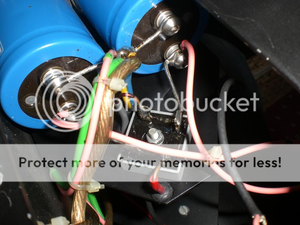
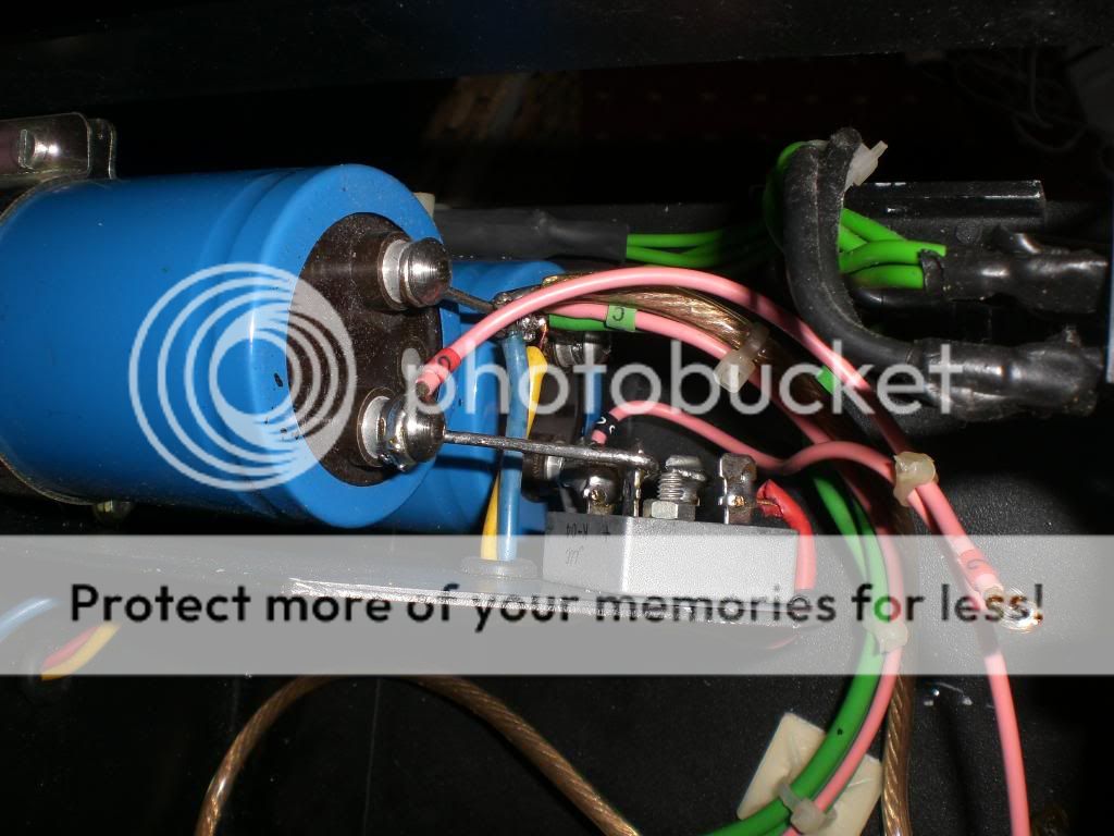
I've added some images of an old bridge rectifier I had spare, the 4 wire pins are the AC input and +/- DC output to the caps. The ~ symbols are where the transformer secondaries attach (2 of the usual 4 wires the other 2 connect to earth). The +/- leads attach to the +/- of the caps, don't get this wrong or it'll be messy and expensive!


Here's images from another Crimson amp (same internals different case) showing the rectifier installed.
The red and grey wires are AC from the secondary the blue and yellow are the other ends of the secondaries connected to earth and the other cap terminals.
You'll need a serious soldering iron for this kind of work (120 - 150W at least) and a smaller 25W for signal cable connections.
A 35-0-35 power supply is theoretically capable of producing around 150W into 8 ohms even if the amp is rated at 60-70W this is essentially dynamic power (always worth having 😀)
The other thing to watch out for is the transformer regulation, the specified secondary voltage is usually with the transformer under load so at low powers it will be up to 5% higher, with a 300VA transformer up to 37V
I'd recommend using supply voltages 10% less than the maximum specified so as the amp isn't stressed for the sake of a few extra watts, the ability to deliver lots of amps is every bit as important as volts.
I've added some images of an old bridge rectifier I had spare, the 4 wire pins are the AC input and +/- DC output to the caps. The ~ symbols are where the transformer secondaries attach (2 of the usual 4 wires the other 2 connect to earth). The +/- leads attach to the +/- of the caps, don't get this wrong or it'll be messy and expensive!


Here's images from another Crimson amp (same internals different case) showing the rectifier installed.
The red and grey wires are AC from the secondary the blue and yellow are the other ends of the secondaries connected to earth and the other cap terminals.


You'll need a serious soldering iron for this kind of work (120 - 150W at least) and a smaller 25W for signal cable connections.
Thanks again for that, your input is greatly appreciated.
I am slowly getting an understanding now.
I am hoping to do this toward the end of the month and get everything ordered up.
Could any one confirm what I should order for the bridge rectifier please?
i.e. best cap/diodes?
Craig
I am slowly getting an understanding now.
I am hoping to do this toward the end of the month and get everything ordered up.
Could any one confirm what I should order for the bridge rectifier please?
i.e. best cap/diodes?
Craig
25A or 35A 200V or 400V or 600V bridge rectifier.
Post18 shows the Main Audio Ground (MAG) soldered onto the wire connecting the smoothing capacitors.
DO NOT copy this.
Locate the MAG near the power amplifiers and the Speaker Terminals. Bring single wire connections from all the various parts of the circuit to this MAG. Bring the PSU Zero Volts to the MAG.
- Status
- Not open for further replies.
- Home
- Design & Build
- Parts
- Where to start?