Is there any one who know where the best place to put the caps and snubbers is? In the box with the NIGC or in the box with trafo and rectifiers? I have two boxes.
snubbericed?
If you are using (snubberized) 2,200uf caps on the chips, there's no problem at all to use a completely separated PSU.
Put the trafo, rectifiers, big caps+snubber on the PSU box.
If you are using (snubberized) 2,200uf caps on the chips, there's no problem at all to use a completely separated PSU.
Put the trafo, rectifiers, big caps+snubber on the PSU box.
I have just 100uf +100nf on the chips, using the first version of PSU+snubbers. Does this make any difference? Is cabling from PSU to amp important or not? I have built the clone exactly as Nat.Sem LM 3875 suggest besides the PSU.
bjengi said:I have just 100uf +100nf on the chips, using the first version of PSU+snubbers. Does this make any difference? Is cabling from PSU to amp important or not?
With an external PSU yes, it makes a difference.
In this case, 100uf on the chip is not enough for the current demands, bass will suffer.
I tested that. That's why I went to higher value caps on the chips and snubberized.
I would recommend that if you had everything integrated on a single board. But that would be a big board, with several big caps.
Excluding the 'everything on one board' approach I recommend bigger (1,000~2,200uf) caps, snubberized, on the chips.
I have a question to Carlos.
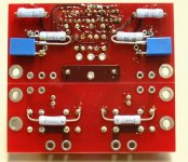
I've managed to place 6.800 mF caps just next to the chip on Peter's LM4780 board (see pics). I also put the snubber right on the caps pins. And now I have a question. Do I miss anything on the board? Can I leave out all the other bypass caps which are in the original layout from Carlos? 😕
Thanks🙂
I've managed to place 6.800 mF caps just next to the chip on Peter's LM4780 board (see pics). I also put the snubber right on the caps pins. And now I have a question. Do I miss anything on the board? Can I leave out all the other bypass caps which are in the original layout from Carlos? 😕
Thanks🙂
Attachments

vasja said:I have a question to Carlos.
I've managed to place 6.800 mF caps just next to the chip on Peter's LM4780 board (see pics). I also put the snubber right on the caps pins.
Cool.
But you should listen to that amp with 20,000~30,000uf capacitance per rail and the new values, as on the latest snubberized PSU.
It's a good upgrade.😉
Nevermind, now to answer your question.
vasja said:Do I miss anything on the board? Can I leave out all the other bypass caps which are in the original layout from Carlos? 😕
Who, me?

Notice that you have a good place to put the 100nf caps, you just need to place the snubbers with another orientation.
Also, the 330nf cap between the rails I use (on those boards) directly on the chip's pins, under the circuit.
Thanks Carlos🙂
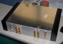
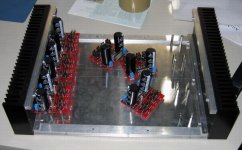
I'll use 20.000 mF with the new LM4780 board from Peter🙂 There, if mounted on the bottom side of the PCB, it is possible to use 2x10.000 mF on the chip's board and another 2x10.000 mF or even more on the rectifier board. As for the pics from my previous posts, this is one of the six channels for my home cinema setup😀
I'll use 20.000 mF with the new LM4780 board from Peter🙂 There, if mounted on the bottom side of the PCB, it is possible to use 2x10.000 mF on the chip's board and another 2x10.000 mF or even more on the rectifier board. As for the pics from my previous posts, this is one of the six channels for my home cinema setup😀
Attachments

- Status
- Not open for further replies.
- Home
- Amplifiers
- Chip Amps
- Where put the snubbericed PSU