Hello all,
Just want to preface this post by saying i have very little experience
building or repairing any tube gear, so i’m reaching out to the experts for help.
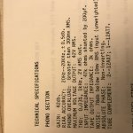
My objective here is to lower the capacitance load my MM phono cartridge sees. According to its specs, it likes 100pF. As things are right now, the 1.2 meter cable and the tone arm wiring are 200pF. Additionally my preamp’s (MFA Magus) phono section has 200pF shunted by 47K according to the manual. So total it’s 400uF not including any Miller Capacitance. I can swap out or shorten the cable as i don’t need 1.2 meters and knock off 100pF.
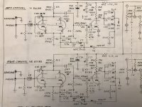
My issue is the caps in the phono section. I’d like to remove them or replace them with a lower value. Only trouble is i can seem to locate them, either by looking at the board or the schematic. The closest i’ve seen is a pair of .22k caps (C3 & C 11). I’m attaching the schematic hoping someone can take a look and advise. I’d appreciate any guidance. Thanks
Just want to preface this post by saying i have very little experience
building or repairing any tube gear, so i’m reaching out to the experts for help.
My objective here is to lower the capacitance load my MM phono cartridge sees. According to its specs, it likes 100pF. As things are right now, the 1.2 meter cable and the tone arm wiring are 200pF. Additionally my preamp’s (MFA Magus) phono section has 200pF shunted by 47K according to the manual. So total it’s 400uF not including any Miller Capacitance. I can swap out or shorten the cable as i don’t need 1.2 meters and knock off 100pF.
My issue is the caps in the phono section. I’d like to remove them or replace them with a lower value. Only trouble is i can seem to locate them, either by looking at the board or the schematic. The closest i’ve seen is a pair of .22k caps (C3 & C 11). I’m attaching the schematic hoping someone can take a look and advise. I’d appreciate any guidance. Thanks
Attachments
 Moved to Analogue Line Level
It looks like they are optional plugins into an external Loading socket. If present I would just remove them. You already have too much.
No. According to your schematic there should be 2 additional RCA jacks labeled as 'LOADING'. That is where additional load resistors and the capacitors would be connected. Do you see the jacks? Is there anything plugged into them? If there's nothing connected then you already have NO additional loading capacitance. If there is then unplug them to remove the extra capacitance.

No I don't mean C3 and C11. Those are nowhere near the input, and nowhere near the Loading socket. Strange question. I expressed myself clearly.
Last edited:
Yes I see the additional loading jacks. I'm using them now to load down the resistance from 47K.No. According to your schematic there should be 2 additional RCA jacks labeled as 'LOADING'. That is where additional load resistors and the capacitors would be connected. Do you see the jacks? Is there anything plugged into them? If there's nothing connected then you already have NO additional loading capacitance. If there is then unplug them to remove the extra capacitance.
However the manual states the input capacitance is 200pf without adding anything additional through the jacks. So i was assuming there are a pair of 200pf caps soldered onto the board just as there are a pair of 47K resistors. These are the caps i'd like to locate and remove.
Please excuse my ignorance as this is all new stuff to me. Thanks
I suspect the stated input capacitance is the internal capacitance of the circuit/tubes. It's inherent to the devices. You can't lower it, only add to it. You can't remove any other caps from the circuit either. They are all needed either for coupling, compensation or RIAA filtering. I wouldn't fret too much over a few pF, it won't make that much difference. Changing the resistance slightly will make a much bigger change in sound, if that's what you're after. Or a different pre.
*Edit: Just noticed you said you're "loading it down" using resistors in the jacks, what resistors are in the jacks? What cart are you using? The pre has built in 47K. Why do you think you need to load it down? Have you tried it with just the standard 47K?
*Edit: Just noticed you said you're "loading it down" using resistors in the jacks, what resistors are in the jacks? What cart are you using? The pre has built in 47K. Why do you think you need to load it down? Have you tried it with just the standard 47K?
Last edited:
The 200pF input capacitance is due to the tubes and circuit topology chosen in the design.
It can't be reduced.
It can't be reduced.
Capacitance is everywhere. There's some inside the input tube. This is multiplied by stage gain, "Miller". We expect about 90pFd from this cause alone. We expect another 90pFd from 3 feet of cable. And a few dozen pFd of "stray". That's why "most... 200-300pf".the manual states the input capacitance is 200pf without adding anything additional through the jacks. So i was assuming there are a pair of 200pf caps
BUT. Never trust the data sheet. The guy who writes these may not be talking to the guy who built or designed the electronics. Here we have C40, a stunning 10pFd of added capacitance, Miller-ed. That may be 500pFd right there. Each unit of 12AX7 has 1.7pFd, Miller-ed.... and they put both sections in parallel!
IF this much is true (don't trust the schematics either), then you have over 600pFd before you add the cable. Even an old Grado may be dulled by that much capacitance.
Why not cut-out those 10pFd? Typically such caps are added ad-hoc to reduce oscillation or radio interference. (Note the high part-number, 40 may be that last part added when it squealed in use.) You could be sorry.
If you truly need <100pFd, this may not be the preamp for you.
That's what i thought may be the case after reading yours and others replies. The cartridge is a ClearAudio Maestro. Things were sounding a bit bright with 47K and the 400pF of capacitance so i wanted to 'tone' things down. I have 150K resistors there now bringing the resistance down to 35K and there was an improvement. I like the preamp, tonearm and cartridge, so i'm not looking to change any components now. Just trying to learn things and improve what I have.I suspect the stated input capacitance is the internal capacitance of the circuit/tubes. It's inherent to the devices. You can't lower it, only add to it. You can't remove any other caps from the circuit either. They are all needed either for coupling, compensation or RIAA filtering. I wouldn't fret too much over a few pF, it won't make that much difference. Changing the resistance slightly will make a much bigger change in sound, if that's what you're after. Or a different pre.
*Edit: Just noticed you said you're "loading it down" using resistors in the jacks, what resistors are in the jacks? What cart are you using? The pre has built in 47K. Why do you think you need to load it down? Have you tried it with just the standard 47K?
Thanks
Yes that's what i thought might be the case. Thanks.The 200pF input capacitance is due to the tubes and circuit topology chosen in the design.
It can't be reduced.
Thanks for taking the time to illustrate. Just curious, how does 10pF become 500pF?Capacitance is everywhere. There's some inside the input tube. This is multiplied by stage gain, "Miller". We expect about 90pFd from this cause alone. We expect another 90pFd from 3 feet of cable. And a few dozen pFd of "stray". That's why "most... 200-300pf".
BUT. Never trust the data sheet. The guy who writes these may not be talking to the guy who built or designed the electronics. Here we have C40, a stunning 10pFd of added capacitance, Miller-ed. That may be 500pFd right there. Each unit of 12AX7 has 1.7pFd, Miller-ed.... and they put both sections in parallel!
View attachment 1069183
IF this much is true (don't trust the schematics either), then you have over 600pFd before you add the cable. Even an old Grado may be dulled by that much capacitance.
Why not cut-out those 10pFd? Typically such caps are added ad-hoc to reduce oscillation or radio interference. (Note the high part-number, 40 may be that last part added when it squealed in use.) You could be sorry.
If you truly need <100pFd, this may not be the preamp for you.
how does 10pF become 500pF?
Miller Capacitance
- Home
- Source & Line
- Analog Line Level
- Where are input capacitors for MFA Magus phono stage