Quite Right...... but my version of higher screen volts than the anode offers lower thd than true triodes ! It suggests the tube electrode spacings aren't optimal for low distortion audio but permissible for video lineTV.
I tried ECL82 pentodes to prove that point and none of the screen benefits arise. The fact that this pentode has a screen grid optimised for o/p stage audio work (same as anode) and isn't influenced by having higher volts on the screen.
Those who listened to amps using both triode and conjugated CCS circuits couldn't detect any quality differences.....Question is, is it worth the massive complication of implementing screen CCS's ? No, unless serious drive swing voltages are required and when global nfb rescues many of the ills in p-p amps. The voltage tied CCS in the diff cathodes does offer superb performance.
High gm, 6CH6, 12BY7, 12HG7 and others work well.
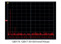
The attached spectrum shows my circuit showing more third harmonic (F3) AND F2 has been effectively cancelled by the CCS in the cathode. > this is correct for perfect signal balance also benefitting from regenerative feedback to the grids. Triodes should display more F2 but this circuit produces odd harmonics sim to UL circuits. Hence the mixed terminology.
My conclusion is that using the screen grid in a tube for a purpose which is hasn't been specifically designed for is interesting, that is the AC signal shared between screen and anode and yet the DC conditions are so wildy apart.
None of this appears in the Radiotron handbook, or does it ?
All those TV designated tubes one thought weren't suitable for audio work with a CCS have a new lease of life in front of them, and most have generous ratings and will last a very long time.
richy
I tried ECL82 pentodes to prove that point and none of the screen benefits arise. The fact that this pentode has a screen grid optimised for o/p stage audio work (same as anode) and isn't influenced by having higher volts on the screen.
Those who listened to amps using both triode and conjugated CCS circuits couldn't detect any quality differences.....Question is, is it worth the massive complication of implementing screen CCS's ? No, unless serious drive swing voltages are required and when global nfb rescues many of the ills in p-p amps. The voltage tied CCS in the diff cathodes does offer superb performance.
High gm, 6CH6, 12BY7, 12HG7 and others work well.
The attached spectrum shows my circuit showing more third harmonic (F3) AND F2 has been effectively cancelled by the CCS in the cathode. > this is correct for perfect signal balance also benefitting from regenerative feedback to the grids. Triodes should display more F2 but this circuit produces odd harmonics sim to UL circuits. Hence the mixed terminology.
My conclusion is that using the screen grid in a tube for a purpose which is hasn't been specifically designed for is interesting, that is the AC signal shared between screen and anode and yet the DC conditions are so wildy apart.
None of this appears in the Radiotron handbook, or does it ?
All those TV designated tubes one thought weren't suitable for audio work with a CCS have a new lease of life in front of them, and most have generous ratings and will last a very long time.
richy
Attachments
Quite Right...... but my version of higher screen volts than the anode offers lower thd than true triodes ! It suggests the tube electrode spacings aren't optimal for low distortion audio but permissible for video lineTV.
Had a look-see at the characteristics. I suspect that what you have there is a video amp type that was intended for B & W TV sets that didn't use a PTX. When reliable Si power diodes became available in the mid-1960s, TV PTXs went away (for B & W anyway, color TVs were still power hungry beasts and still needed PTXs -- usually 200Vrms units running into full wave, solid state, voltage doublers -- had one of these, but it was poofed, oh well, at least I recovered the lams). The video amps ran the screens directly off the line voltage supply, and the plate voltages had to be lower than the screen voltages due to the plate load. These were filled with lots of VTs with weird heater voltages for series operation off the AC mains. Later versions used lots of "Compactrons" that combined as many functions (dual, RF pentodes for IF strips, dual and triple triodes for horizontal oscillator, sync sep duty, HD PAs and damper diodes) in one bottle as possible.
The CRTs were likewise designed to operate the anodes off low voltage DC with the difference being made up with very large post deflection acceleration, since there was no lack of huge voltages from flyback xfmrs.
A little innovation. The ultimate UL driving stage is to connect a CCS to the screen of a 12BY7 (6CH6 shown here) which limits the screen about 5mA to a higher voltage feed than the anode supply is. Connect a high value cap from the screens to the anodes and the ideal U Linear stage is born.
Yuck.
Suicide biased screen means any process variation (difference in grid alignment, grid leakage, secondary emission, etc.) or temperature drift (I hope you don't use one of those awful SS current sources based on a BJT with constant base voltage, or worse yet, a depletion mode FET!) results in wildly different screen voltage swings, taking it somewhere between saturation of the tube and saturation of the CCS.
With no stable bias point, the amount of swing available before either saturates is unpredictable at best. Note that an ideal CCS might not perform too badly: it would at least be linear by itself. As the plate voltage rises, dragging the screen up, the CCS will easily experience reverse voltage, which for a typical transistor CCS means forward-biasing something normally reversed. In the best of cases, a diode steps in, either shorting out the CCS, or disconnecting it. In the worst of cases, a junction that's not normally supposed to be reversed goes avalanche and explodes.
Your circuit blatantly flaunts the negative resistance characteristic of the screen grid. It will make an excellent flip-flop.
Tim
If the plate and screen are always at the same potential, it won't poof. (Reference Tubelab's experiments with pseudotrioded 6AV5s and his screen voltage spec busting by huge margins.)
This is NOT a universal truth. I have got the blown tubes to prove it. Neglecting the DC resistance of the OPT, when the volume is turned all the way down the tube doesn't know or care if it is triode, pentode or UL wired. Many tubes get unstable at high screen voltages. The tube can rock all day, but may slowly (or rather quickly) run away into the red zone at idle.
Yes the 6AV5GA can eat far more than its rated screen voltage in triode mode. I did note a fairly wide variation amongst the different construction of 6AV5GA's with the square box plate Sylvanias capable of the most abuse.
In the same series of experiments I noted that the 6CD6 is from the other end of the spectrum. Even triode connection will not stop a runaway condition without signal.
I have seen runaway with the 6LW6 in triode too. I was quite a bit over spec though.
"Suicide biased screen ..."
One could use a gyrator type CCS to hold the screen voltage at some set DC level. Two long time constants (the other from the 1.0 uF screen cap) could make for some real gyrations though.
Seems that the enhanced triode (elevated screen) would postpone plate current saturation at high plate current, so it would hold off sat. distortion longer. As long as the g2 doesn't get fried at idle.
Normal UL mode provides the same sat. enhancement only when needed (at high plate current), so is less dangerous for g2 at idle. Or should I say, less stressful for g2 at idle.
Last edited:
Gyrations... it might generate them itself if it dips too far into the negative resistance region. I'd suggest an old fashioned LC filter, but it would make a good series resonant tank!
No, the negative resistance isn't THAT bad at nominal operating point, but if it gets forced into that condition (say by a combination of overdrive plus odd duty cycle signals), it could shoot right down and latch or start kicking. Better to have an impedance lower rather than higher, since it's easier to avoid crossing through the negative-plus-positive-resistance-equals-infinity region. Also better to have a real rather than complex impedance, since it won't be prone to oscillation (i.e., nix the plate-screen cap).
If you want to limit screen current, a series resistor and small bypass cap is perfectly acceptable; in my class D amplifier, I used a time constant sufficiently short to accommodate the audible range, while bypassing the RF. The result? Crisp, flat square waves, reasonable performance at all duty cycles (typical on-resistance of ~100 ohms for 38HE7), and no toaster grids.
Tim
There is nothing like innovation, however, justifying the amount of time burning the midnight oil honking about with sweep & video tubes, now I can see some having a fresh lease of working life working in audio rather than RF. Gradually, I will go though the stillage of redundant TV tubes to find suitable candidates.
That Williamson driver circuit I provided is in some ways ripping part of the tube book out of the window in forcing a tube suit a particular application. There are two limiting factors, electrode dissipation and many of these tubes have relatively sharp and low Vg to Vcath cutoff points. This cutoff nastiness is the bit to watchout and with the circuit I provided is to make sure the AC peak voltage swing on the screen doesn't approach the CCS voltage supply (so I put in the AC voltage levels for clarity) where instability can occur.
Note comment in Morgan Jones 4th ed Valve amps ref page 133 and esp the comment on p.140. The use of such a HV would ruleout integrated chip sources.
The CCS for the screen is a simple two transistor HV pnp. A fantastic amount of AC invisible impedance isn't required, i.e a minimum configuration to avoid oscillation and the inbuilt ft limitation of the pnp acts as a capacitive damper. The curtailing parameter is the HV pnp rating and a bit of wattage and to make sure the screen supply comes up the same time or later than the anode.
The screen to anode coupling cap adds another dominant LF pole in adddition to the others provided in any R/C circuit and in conventional p-p amps often near impossible to avoid them altogether. The AC impedance of the screen can be easily worked out; the 2uF used will see a -3dB point around 5Hz but should another pole interact with others in a conventional push pull amp ?
Bode plot shows no problem, however, in the back of my mind something tells me that with two push-pull amps one with the modified driver using identical op/ transformers, Will they have near identical spectral performances ? Mathematically working the F2-F7 harmonics (Radiotron hand book); the effects of global nfb is so dramatic on the overall amp performance, and I think so. The starting point is that THD will be already very low, but the variable is the amount of global nfb effecting the higher order harmonics and how they effect sonically ......
richy
Note comment in Morgan Jones 4th ed Valve amps ref page 133 and esp the comment on p.140.
Us mere mortals can't note the comments in a book that isn't released until Nov. 26.
Haven't you bought Jack Bybee's Temporal Translator? It uses quantum physics to sidestep causality.
bought Jack Bybee's
Those words don't fit together in my vocabulary.
Sorry, if some of his stuff cost a few $ I could consider experimenting, but things that cost $100 or more better do something that's measureable and useful, like.....an OPT or something like that. I don't even buy $100 tubes that are known to be excellent and have all the usual audiophool words just dripping from the pins!
Us mere mortals can't note the comments in a book that isn't released until Nov. 26.
Apologies... erratum should have read 3rd edition
richy
Apologies... erratum should have read 3rd edition
I thought maybe you got a sneek peek......or your very own version of Jack Bybee's Temporal Translator
There is a picture of the front cover of the 4th edition posted on Amazons web site with the November release date.
- Status
- Not open for further replies.
- Home
- Amplifiers
- Tubes / Valves
- When can screen voltage be higher than plate???