Due to my very limited knowledge I cannot contribute with anything that would be of interest here, but I find the discussion now really interesting to follow. Thank you guys.
And, we are missing Charles Hansen here, don't we?
Saluti, Tino
john curl said:I built what I previously described, as an open loop line preamp, the CTC. 350KHz open loop bandwidth anyone? Yes, I shamelessly copied Charles Hansen of Ayre, who did it first. I was chicken to do it, before I saw that Charles had gotten away with it.
And, we are missing Charles Hansen here, don't we?
Saluti, Tino
To Rodolfo and Ultima:
and
Yes, Rodolfo, it certainly is the basic underlying physics of the different pairs. Without any degeneration to enhance the intrinsic transconductance linearity, they rank worst-to-best in terms of this linearity as bipolar, FET, and vacuum tube.
What's interesting is the fact that some simple degeneration can change this picture, quite radically. My suggestion yesterday was aimed at inspiring someone to run a sim to show this, but Ultima's reference to Marshall Leach's front ends serves this purpose quite nicely. It turns out that a bipolar device, with the very high gm, has the lowest dynamic emitter resistance for a given current. So, one can see intuitively that when combined with a fixed external degeneration resistance, the net emitter resistance will be influenced quite strongly. In terms of linearity, this has a very positive effect. This is shown by the curves that Marshall provides for Re = 300 vs. 0. The enhanced linearity is obvious.
A JFET (or MOSFET) will have less gm for the same current, thus the dynamic resistance will be higher, and degeneration, while still useful, won't be as dramatic as it is in the case of the bipolar.
These comments are generalities of course, and will vary in degree with the FET parts (or vacuum tubes) as to the specific unit selected for comparison. But with bipolars, it is simple physics. On the selection, one could select a very high gm JFET part (say the J309 etc.) that might begin to approach a bipolar for the degree of linearity enhancement when degeneration is added. I can't say just how much, but the exercise might be worthwile.
Marshall's data also shows the "TIM spike" of error voltage, a very important point. With bipolars one needs to carefully align the operating points, RC values etc. so as to guarantee that the worst case input step won't slew the amp. With the lower gm parts such as FETs and tubes, this behavior can be automatic.
Hope this is helpful, and thanks to Rodolfo and Ultima for the stimulating comments.
The big question remaining of course, what does all of this mean in terms of how a circuit auditions? If they truly "all sound alike", then it is a moot point. But it also seems obvious that there are legions who feel strongly that they all *don't* sound alike. Maybe the input stage linearity issue could be helpful towards a better overall understanding.
Walt Jung
Good point.
Could it be this is basically unmasking the underlying physical nature of the different devices?
The comparison among BJT and FET I suggested in my previous post.
May be the FET - Tube difference is related to the field dependent dielectric constant of solid state (channel region) with respect to vacuum?
Rodolfo
and
Only me who can't open that PDF file!??
About emitter degenerstion, I just wonder how would a JFET compare to a BJT that has such an emitter degeneration which match the JFET's Gm curve?
The Walt J. Gm curve picture Jan D. first showed here leaded me to think about Leach's worthwhile words about emitter degeneration which can be seen
here
Cheers
Yes, Rodolfo, it certainly is the basic underlying physics of the different pairs. Without any degeneration to enhance the intrinsic transconductance linearity, they rank worst-to-best in terms of this linearity as bipolar, FET, and vacuum tube.
What's interesting is the fact that some simple degeneration can change this picture, quite radically. My suggestion yesterday was aimed at inspiring someone to run a sim to show this, but Ultima's reference to Marshall Leach's front ends serves this purpose quite nicely. It turns out that a bipolar device, with the very high gm, has the lowest dynamic emitter resistance for a given current. So, one can see intuitively that when combined with a fixed external degeneration resistance, the net emitter resistance will be influenced quite strongly. In terms of linearity, this has a very positive effect. This is shown by the curves that Marshall provides for Re = 300 vs. 0. The enhanced linearity is obvious.
A JFET (or MOSFET) will have less gm for the same current, thus the dynamic resistance will be higher, and degeneration, while still useful, won't be as dramatic as it is in the case of the bipolar.
These comments are generalities of course, and will vary in degree with the FET parts (or vacuum tubes) as to the specific unit selected for comparison. But with bipolars, it is simple physics. On the selection, one could select a very high gm JFET part (say the J309 etc.) that might begin to approach a bipolar for the degree of linearity enhancement when degeneration is added. I can't say just how much, but the exercise might be worthwile.
Marshall's data also shows the "TIM spike" of error voltage, a very important point. With bipolars one needs to carefully align the operating points, RC values etc. so as to guarantee that the worst case input step won't slew the amp. With the lower gm parts such as FETs and tubes, this behavior can be automatic.
Hope this is helpful, and thanks to Rodolfo and Ultima for the stimulating comments.
The big question remaining of course, what does all of this mean in terms of how a circuit auditions? If they truly "all sound alike", then it is a moot point. But it also seems obvious that there are legions who feel strongly that they all *don't* sound alike. Maybe the input stage linearity issue could be helpful towards a better overall understanding.
Walt Jung
Diff amps with compound pairs
There's another possibility too. Back in this post http://www.diyaudio.com/forums/showthread.php?postid=484775#post484775 the use of compound pairs was brought up. To get equal gm between the normal BJT diff amp and the one with the compound pair, the re of the transistor in the normal BJT diff amp had to be added to the fixed RE of the compound pair to get the same small-signal gm. Linearity seemed improved over the normal degenerated BJT input stage. I think the Halcro uses the compound pair for its input diff amp.
There's another possibility too. Back in this post http://www.diyaudio.com/forums/showthread.php?postid=484775#post484775 the use of compound pairs was brought up. To get equal gm between the normal BJT diff amp and the one with the compound pair, the re of the transistor in the normal BJT diff amp had to be added to the fixed RE of the compound pair to get the same small-signal gm. Linearity seemed improved over the normal degenerated BJT input stage. I think the Halcro uses the compound pair for its input diff amp.
What is the CTC?the CTC
I don't know the theory much, but from experimenting differential without RE degeneration seems always sounds better. Maybe it is not so linear, maybe the distortion is higher, I dont know. In complete audio amp, with adjusting here and there (still using no degeneration). Problem is with bipolar. I usually use RE of 22ohm. Bipolar differential without this small RE degeneration gives too bright sound.The big question remaining of course, what does all of this mean in terms of how a circuit auditions
PMA,
NE5532 is a dual opamp. If I built a line driver, one opamp is for gain stage, and the other is only used for buffer, (but the buffer is excluded from the gain stage, just a buffer outside the other opamp) will this help compared not using buffer at all?
Andy C:
Wow, it certainly seems like this thread has drifted a ton since this posting. But that's another issue, I guess.
This is a good idea in principle, and I for one would like to see it optimized further, at some point. It does introduce a whole new set of variables beyond the comparison of the various device gm linearities. I'm not so sure that everyone's ready to make the leap. The fact that the discussion died out on taking the compound pair further seems to suggest that.
Not "seemed", it is. This is obvious from comparison of the V2 and V6 curves, towards the end points.
I don't know what this snippet does for us. We don't know the details of just how it is realized, so any conclusions would be suspect, in my view. Is it bipolar or FET based? Operating points? Difficult to say, for sure.
Walt Jung
There's another possibility too. Back in this post http://www.diyaudio.com/forums/show...4775#post484775 the use of compound pairs was brought up. To get equal gm between the normal BJT diff amp and the one with the compound pair, the re of the transistor in the normal BJT diff amp had to be added to the fixed RE of the compound pair to get the same small-signal gm.
Wow, it certainly seems like this thread has drifted a ton since this posting. But that's another issue, I guess.
This is a good idea in principle, and I for one would like to see it optimized further, at some point. It does introduce a whole new set of variables beyond the comparison of the various device gm linearities. I'm not so sure that everyone's ready to make the leap. The fact that the discussion died out on taking the compound pair further seems to suggest that.
Linearity seemed improved over the normal degenerated BJT input stage.
Not "seemed", it is. This is obvious from comparison of the V2 and V6 curves, towards the end points.
I think the Halcro uses the compound pair for its input diff amp.
I don't know what this snippet does for us. We don't know the details of just how it is realized, so any conclusions would be suspect, in my view. Is it bipolar or FET based? Operating points? Difficult to say, for sure.
Walt Jung
lumanauw said:PMA,
NE5532 is a dual opamp. If I built a line driver, one opamp is for gain stage, and the other is only used for buffer, (but the buffer is excluded from the gain stage, just a buffer outside the other opamp) will this help compared not using buffer at all? [/B]
You can try it, but according to my experience the standard opamp was unable to substitute the buffer circuit like BUF634 or LT1010. I would also strongly recommend to you to leave the NE5532 and better try OPA2134 for example.
WaltJ said:
This is a good idea in principle, and I for one would like to see it optimized further, at some point. It does introduce a whole new set of variables beyond the comparison of the various device gm linearities. I'm not so sure that everyone's ready to make the leap. The fact that the discussion died out on taking the compound pair further seems to suggest that.
Hmm, i know this kind of diffamp as CFP-Input, and it's not something
new. The CFP does a good job in linearizing the diffamp, but also
adds additional pole. I have built an amp using cfp, but never got
it really good sounding. I think this kind of input is most interesting
for circuits without global feedback.
If i remember correct D.Self has written about the cfp-diffamp.
There is one thing i don't understand: When you talk about diffamps,
and show transfercurves and measurements you use inputvoltages
like +/- 0.5v. But in an amp with global feedback input is more about <1mv ?
In this area a diffamp is already very linear ?
Mike
WaltJ said:I don't know what this snippet does for us. We don't know the details of just how it is realized, so any conclusions would be suspect, in my view. Is it bipolar or FET based? Operating points? Difficult to say, for sure.
I've got the PDF of the Halcro schematic at home, but I don't think it has component values. The input stage is bipolar though. The PDF is straight from the patent. I mainly added that as a parenthetical comment, not as any kind of "appeal to authority" type of argument - except in the sense that it is being used in some production design. Nor was I asking anyone to "make the leap" as it were. Were you expecting anyone to "make the leap" when you posted the vacuum tube diff amp results? I think you were just posting it as an illustration of what's possible. And that's all I was doing.
Hmm, i know this kind of diffamp as CFP-Input, and it's not something
new. The CFP does a good job in linearizing the diffamp, but also
adds additional pole. I have built an amp using cfp, but never got
it really good sounding. I think this kind of input is most interesting
for circuits without global feedback.
This is a semantic question. So, does CFP-Input mean complementary feedback pair-Input? Why not just say that?
Unquestionably it does linearize things, Yes, and it adds phase shift. All must be managed.
Yes, it can be designed with low enough distortion to be used with zero global feedback. I remember doing an audio line receiver in the early seventies using the concept.
If i remember correct D.Self has written about the cfp-diffamp.
Do you have a reference, perhaps?
There is one thing i don't understand: When you talk about diffamps,
and show transfercurves and measurements you use inputvoltages
like +/- 0.5v. But in an amp with global feedback input is more about <1mv ?
In this area a diffamp is already very linear ?
Mike
Well, you certainly need to look at the extended dynamic range if you plan on using no global feedback. But, even if you do use global feedback, it is valid to compare input stages over wide ranges. The best performers will show the best linearity around the zero (balance) point. No, I don't think it can be said that a bipolar diff pair is really linear, unless you restrict the input to a few microvolts around the balance point. Even then, if you do a valid comparison, the other active device types will still be shown to be more linear.
Walt Jung
I've got the PDF of the Halcro schematic at home, but I don't think it has component values. The input stage is bipolar though. The PDF is straight from the patent. I mainly added that as a parenthetical comment, not as any kind of "appeal to authority" type of argument - except in the sense that it is being used in some production design. Nor was I asking anyone to "make the leap" as it were. Were you expecting anyone to "make the leap" when you posted the vacuum tube diff amp results? I think you were just posting it as an illustration of what's possible. And that's all I was doing.
Andy, I didn't really mean to sound argumentative, and if you took it that way, sorry. But hey, why not at least post the patent #, that would be helpful to all, wouldn't it?
As for the vacuum tube (VT) vs. the others, the only "leap" I expected the forum to make was that linear is linear, and if that's what you seek, the VT is the best (at least for the types shown, and within the modeling limits). Is it too much of a stretch to imagine that one aspect of the continuing appeal of the vacuum tube for audio amps is rooted in the intrinsic linearity?
Walt Jung
WaltJ said:Andy, I didn't really mean to sound argumentative, and if you took it that way, sorry. But hey, why not at least post the patent #, that would be helpful to all, wouldn't it?
I'm at work now. But after I get home I can email the PDF to anyone who requests it. Thanks for understanding.
Hi Walt !
I would need to search the net, what i remember is, that D.Self
suggests 2.2k as resistor between base of CFP-bjt and collector
of input-bjt.
BTW, the input-bjt can be replaced by jfet, giving you without
degenerationresistors gm's far above any bjt. I had some good
result with this combination, but without RE's i am stuck to asymetrical
circuits. Somehow i am in love with full complementary circuits.
This complementary-feedback-pair can be used to substitute other
transistors, often it's used in outputstage.
My thought about measuringranges was, to look only at these ranges
devices are used in normal operation. With high feedback the diffamp
can operate with a few uV, but you are right, any device get's lowdistortive
if used in such small range.
Mike
Halcro patent info
Here's a link to Charles Hansen's post with info on the Halcro patent. http://www.diyaudio.com/forums/showthread.php?postid=410605#post410605
Walt, you have mail.
Here's a link to Charles Hansen's post with info on the Halcro patent. http://www.diyaudio.com/forums/showthread.php?postid=410605#post410605
Walt, you have mail.
patent 6,600,367?
http://patft.uspto.gov/netacgi/nph-...&d=PTXT&p=1&p=1&S1=Halcro&OS=Halcro&RS=Halcro
JF
http://patft.uspto.gov/netacgi/nph-...&d=PTXT&p=1&p=1&S1=Halcro&OS=Halcro&RS=Halcro
JF
Attachments
Halcro
I have red the Halcro patent, number 6,600,367 , before, and one thing that amzaed me allready then, is... can the patent owner really claim to have right to be the only one who can use for instance transistors with fo > 500 MHz in poweramplifier designs such as the text copy below tells (you find it in the end of the link-page given above)?? 😕
"For integrated circuit operational amplifiers, wideband could be considered to be a gain bandwidth product of more than 100 MHz, high gain means an open loop gain of more than say 100 V/V, and a wideband transistor is a device with a transition frequency exceeding 500 MHz"
I admit I don't know how to interpret patent text's.
/Michael
The only independent claim in that patent is Claim 1:
What that means is that all other claims are about an amplifier described in Claim 1. So that patent covers any amp with ALL the features called out in that claim; further claims refine this, for example:
So all he claims is that he's the first to conceive of using transistors with fo>500MHz in an amp having all the features of Claim 1.
What is claimed is:
1. An electronic amplifier having an input, and an output, and including an output stage containing output transistors being connected to the amplifier output,
the output stage including an output error correction stage containing a first amplifier and a second amplifier, an input to the output stage being connected to an input of the first amplifier,
wherein there are at least four local negative feedback paths,
a first local negative feedback path being between an output of the output stage and an input of the first amplifier,
a second local negative feeback path being between an output of the first amplifier and an input of the first amplifier,
and a third local negative feedback path being between an output of the output stage and an input of the second amplifier and,
a fourth local negative path being between an output of the second amplifier and an input of the second amplifier,
an output of the first amplifier being connected to an input of the output stage transistor buffers or output stage transistors through a first network,
an output of the second amplifier being connected to an input of output stage transistor buffers or output stage transistors through a second network,
such that the first network transfers high frequencies from the first amplifier to an input of output stage transistor buffers or output stage transistors more substantially than the second network,
and the second network transfers low frequencies from the second amplifier to the input of output stage transistor buffers or output stage transistors more substantially than the first network, such that components of the first and second amplifier, first, second, third and fourth local negative feedback paths, first and second networks, and output transistors and output stage transistor buffers, are selected to form a substantially second order local dominant pole,
and an input stage, wherein the input stage includes a current mirror and a voltage amplification stage, an output of the input stage being connected to the input of the output stage,
and the first and the second amplifier being supplied by power from a floating power supply means coupled to either an or the output of the output stage so that a voltage of floating power supply supplying the first amplifier and second amplifier will follow substantially an output voltage of the output stage.
What that means is that all other claims are about an amplifier described in Claim 1. So that patent covers any amp with ALL the features called out in that claim; further claims refine this, for example:
2. An electronic amplifier as defined in claim 1 wherein the first amplifier is a first wideband differential operation amplifier.
So all he claims is that he's the first to conceive of using transistors with fo>500MHz in an amp having all the features of Claim 1.
Still, coming back to the issue of linearity differences between bjt and fet, I am not convinced that there is such a difference when you level the playing field. Look at the two plots from Walt. Sure, the bjt LOOKS less linear by itself, but with a bit of emitter degeneration it looks pretty much the same (bottom) as the fet (top), if not better.
It probably is not very relevant to compare these devices stand-alone, as they can be used in a circuit with largely equivalent results.
So, if the linearity *in the application* is pretty much the same, what would then be the cause of audible differences, if there indeed are any. Is there a difference in parasitic capacitance modulation? If we then go to cascodes, does the audible difference disappear? I know, questions, questions, but the linearity differences don't seem to be the root cause.
Jan Didden
Attachments
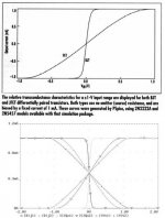
The previous reference to Leach's page here http://users.ece.gatech.edu/~mleach/lowtim/instage.html shows that the linearity of the BJT diff amp is better than that of the FET diff amp if emitter degeneration is added to make the gm the same for each. That's fine within limits for power amps (the LM3875 has 1k emitter degeneration resistors http://cache.national.com/ds/LM/LM3875.pdf), but for low-noise applications the emitter resistors bork up the noise performance, so you have to leave them out. So for ultimate low noise applications, FETs win on linearity. Where you can give up some noise, BJTs with emitter degeneration win.
Still, coming back to the issue of linearity differences between bjt and fet, I am not convinced that there is such a difference when you level the playing field. Look at the two plots from Walt. Sure, the bjt LOOKS less linear by itself, but with a bit of emitter degeneration it looks pretty much the same (bottom) as the fet (top), if not better.
Jan, it *looks* less linear because it is! It is an inescapable conclusion, backed up by math and measurements. That's for the basic device, sans any degeneration. But you can't talk about the fundamental linearity differences between bipolar and FET, if you degenerate one and not the other... that's apples vs. oranges.
It probably is not very relevant to compare these devices stand-alone, as they can be used in a circuit with largely equivalent results.
It isn't relevant to know beforehand what is the basic linearity of a part before you start designing with it? Huh? I'd say that if you want the highest quality, you'd better know just what the differences in fundamental distortion between various types of amplifying devices really are.
Walt Jung
FET vs. BJT
Now Jan, Why don't you build a phono or line stage with FETs in the input and another one with BJTs as I actually did. Compare the sound of the two and keep the one you like. I preferred the FET one.
Still better build a MC prepre-amp and the difference will be huge.
I compared MAT02 with 2SK389BL. Not the worst BJTs around that MAT02s.
I presume it has something to do with a different transfer function of the FET and the BJT. The latter is exponential, the former square law. Look it up in the OPA604 datasheet. For me such a mathematic explanation does not explain a lot but using my ears........
😉
janneman said:Still, coming back to the issue of linearity differences between bjt and fet, I am not convinced that there is such a difference when you level the playing field. Look at the two plots from Walt. Sure, the bjt LOOKS less linear by itself, but with a bit of emitter degeneration it looks pretty much the same (bottom) as the fet (top), if not better.
It probably is not very relevant to compare these devices stand-alone, as they can be used in a circuit with largely equivalent results.
So, if the linearity *in the application* is pretty much the same, what would then be the cause of audible differences, if there indeed are any. Is there a difference in parasitic capacitance modulation? If we then go to cascodes, does the audible difference disappear? I know, questions, questions, but the linearity differences don't seem to be the root cause.
Jan Didden
Now Jan, Why don't you build a phono or line stage with FETs in the input and another one with BJTs as I actually did. Compare the sound of the two and keep the one you like. I preferred the FET one.
Still better build a MC prepre-amp and the difference will be huge.
I compared MAT02 with 2SK389BL. Not the worst BJTs around that MAT02s.
I presume it has something to do with a different transfer function of the FET and the BJT. The latter is exponential, the former square law. Look it up in the OPA604 datasheet. For me such a mathematic explanation does not explain a lot but using my ears........
😉
- Status
- Not open for further replies.
- Home
- Amplifiers
- Solid State
- "What's your reasoning?" and not "What's your belief?".