I've built a preamp, and it's not working, my amp/speakers do not want this thing in the circuit, bunch of popping, hissing, buzzing.
I have the input, output, DC wired the same as in my previous preamp, which works fine.

I used spare leads from resistors to make some connections in the circuit, could that be a problem? everything seems to be connected correctly.
I used BC547C instead of BC549, but they're basicaly interchangable, as far as i know.
I have the input, output, DC wired the same as in my previous preamp, which works fine.
I used spare leads from resistors to make some connections in the circuit, could that be a problem? everything seems to be connected correctly.
I used BC547C instead of BC549, but they're basicaly interchangable, as far as i know.
BC547C is fine.
Can you take a picture of your construction?
Do your DC voltages match the circuit diagram?
Can you take a picture of your construction?
Do your DC voltages match the circuit diagram?
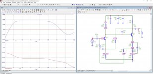
I don't see any power supply decoupling capacitors, and the circuit doesn't have very high power supply rejection
I suggest adding power supply decoupling capacitors first.
I suggest adding power supply decoupling capacitors first.
I agree, this looks like a section and not intended to be used as a "complete" preamplifier.I don't see any power supply decoupling capacitors, and the circuit doesn't have very high power supply rejection
I suggest adding power supply decoupling capacitors first.
It also has very high gain for a line amp and will not accept typical line level signals without severe clipping and distortion. The gain is around 20db (X10 voltage gain)
Oh, makes sense i guess. my previous preamp is connected to DC directly as well, but it works. Probably need to fix that anyway.
The cap is on the other side, because i installed the previous cap in the wrong direction, so was worried it's fried.


The cap is on the other side, because i installed the previous cap in the wrong direction, so was worried it's fried.
Aside from @Mooly comment regarding gain.. you definitely need some local supply decoupling. A 100uF electro and a 100nF ceramic from DC+ to gnd on the board itself, or whatever you have to hand - the exact values don't matter much - might go some way to clearing up the supply noise (and possibly oscillation)
I was redirected to this design, in a previous thread. was told this would work better.
So the problem is, it has no power coupling capacitors, and it can't accept line input directly form a guitar pickup (humbucker meassuring 7.5kohm)?
So i can fix the power input problem.
Can i fix the signal input problem? different input cap?
Or do you have another good, transistor based pre-amp circuit i could build? (12-18V power supplies preferable, since that's what i got, probably have others as well).
Ah. The gain should be okay for a guitar pickup. I don't think you mentioned that.
Add the supply decoupling, and see how it behaves.
Add the supply decoupling, and see how it behaves.
The input impedance isn't all that high as it is set by R1 (150k)... I don't know what would be recommended for your pickup though.
The 0.22uF cap is fine for the input.
Maybe if you tell us what preamp does work then we might spot some obvious differences such as gain and input impedance etc.
The 0.22uF cap is fine for the input.
Maybe if you tell us what preamp does work then we might spot some obvious differences such as gain and input impedance etc.
This is my firs pre-amp


It's the second pre-amp on this page Simple Audio Preamplifiers
No power decoupling capacitors, as you see.
Works fine, usable distortion with guitar volume at 100%, clean signal below 90%.
I want to compare it to this second preamp, but i need to make it work first😀
I did not mentio, for the second circuit, i used a different value set, for 40db gain, table 1 on this page.
Opamp Alternatives
yes, my amp sounds about twice as loud, with my first pre-amp (second circuit posted here), as it does without it.
How many power decoupling caps do i need for my second pre-amp (firs circuit on this page)?
how do i figure out their voltage and capacitance? and do i just install it paralel to the power supply leads?
And, should i change the resistor values, so that gain is 20db, or 30db, rather than 40? would still be louder than the 13db of the first one.
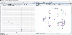
Decoupling caps are usually small in value. A 10uF 25 volt electrolytic should be all that is needed and it is placed across the supply to the preamp.
Its up to you how much gain you need/want and that depends on the level of signal you feed into it. The circuit in post #1 has a gain of 20db, the circuit in post #11 a gain of 13db which is considerably lower.
Its up to you how much gain you need/want and that depends on the level of signal you feed into it. The circuit in post #1 has a gain of 20db, the circuit in post #11 a gain of 13db which is considerably lower.
Thank you, i will try to build you provided circuit.
But are all the capacitors non-polar?
And the ground of the entire circuit, goes to the signal ground terminal on my amplifier, that's fine, right?
And the second (bare/shielding) wire from my power supply should be connected anywhere on the ground wire, right?
But are all the capacitors non-polar?
And the ground of the entire circuit, goes to the signal ground terminal on my amplifier, that's fine, right?
And the second (bare/shielding) wire from my power supply should be connected anywhere on the ground wire, right?
Any caps below 1uF (signal coupling caps) are usually non polar although they certainly don't have to be. Anything large across a rail is usually an electrolytic.
For a simple circuit like this the ground can be taken to any convenient point. If you suspect the power supply is causing problems then try a couple of series connected 9 volt batteries as a test.
For a simple circuit like this the ground can be taken to any convenient point. If you suspect the power supply is causing problems then try a couple of series connected 9 volt batteries as a test.

- Home
- Source & Line
- Analog Line Level
- What's wrong with this preamp circuit?