C7 is polar.
C4 can be polar (its the obvious choice for a 10uF cap) and the plus end goes to the collector of Q2.
R11 needs to be much larger as it is loading the amp severely. Try a 470k, possibly also reducing that 10uF to say a 2.2uF.
C4 can be polar (its the obvious choice for a 10uF cap) and the plus end goes to the collector of Q2.
R11 needs to be much larger as it is loading the amp severely. Try a 470k, possibly also reducing that 10uF to say a 2.2uF.

That looks OK. Simple mono circuits like this are very tolerant of any grounding problems. It should all work.
Thank you, it's hard to put theoretical knowledge into practice. will start building your recomended preamp circuit right now.
Additional question, wiring a volume pot infront of the input will basically function as a gain knob? And i could add mid scoop, trebble bleed circuit, in the same position as well? or should i install volume on input and the effects on the output?
Additional question, wiring a volume pot infront of the input will basically function as a gain knob? And i could add mid scoop, trebble bleed circuit, in the same position as well? or should i install volume on input and the effects on the output?
There is no C2, but i assume it's replaced by V2 (the power supply).
C1 is 220uf, so should it be polar as well?
and last thing, you said " A 10uF 25 volt electrolytic should be all that is needed and it is placed across the supply to the preamp", so should i add that to the circuit, or is that replaced by C7 in the diagram?
Thank you very much for the help
C1 is 220uf, so should it be polar as well?
and last thing, you said " A 10uF 25 volt electrolytic should be all that is needed and it is placed across the supply to the preamp", so should i add that to the circuit, or is that replaced by C7 in the diagram?
Thank you very much for the help
The power supply is normally considered (assumed) to be good and so any decoupling is what we call 'local decoupling' and would normally be a small polar cap. If you want to keep C7 at 220uF then that covers it, it will work just fine.
Adding a volume control at the input doesn't alter the gain of the circuit as such, all it does is attenuate the level supplied to the preamp.
I wouldn't try and add any effects until after you have proved the amp works OK.
Adding a volume control at the input doesn't alter the gain of the circuit as such, all it does is attenuate the level supplied to the preamp.
I wouldn't try and add any effects until after you have proved the amp works OK.
building this thing now.
C7 is 100u polar.
I was asking about C1, 220u should be fine i think.
The majore thing is the C6- 22pf. can i replace it with 47pf, or leave it off?
C7 is 100u polar.
I was asking about C1, 220u should be fine i think.
The majore thing is the C6- 22pf. can i replace it with 47pf, or leave it off?
47pF will work OK. All it will do is roll the HF off a little earlier but it will still extend to around 200kHz before the output is reduced. 47pF is a good value actually.
I would suggest a few things to improve the circuit's power supply rejection:
1. A resistor of maybe 100-220 ohms between the 18V power supply and the circuit, to form an RC filter with C1.
2. Splitting off maybe 10k from R1 and adding another 10µ or so capacitor to ground to form another RC.
BTW, I think it is somewhat mysterious how the first circuit (with much more gain and basically no PSRR) worked fine while the second attempt was such a failure. I can only imagine a bad layout resulting in either a ground loop problem or oscillation. Or did the power supply change between the two? Power supply rejection would only be a minor issue with two 9V blocks, even though batteries actually do exhibit some noise of their own.
Last edited:
I've built the circuit, and it's experiencing the same issues as the first version.
All of the voltages basically check out (8.6 instead of 8.3 on R3 is the biggest difference.
But the voltage at the output keeps jumping from 2.9 to 4.2, like it's oscilating between these voltages.
I used an smd electrolytic 2.2uf, 50V cap, and the voltage right before it is correct value, and stable. Maybe replacing this cap is the first thing to try, since the problem occurs right after it?
I will apply the recomended modifications, and will try to figure out the issue.
I used BC547C resistors, which i've seen used in multiple pre-amp circuits, although they're not technicaly transmitors made for audio use. Should i replace the with BC33725 (BC549 equivalent)? the unstable output voltage seems more important at this moment.
2. Splitting off maybe 10k from R1 and adding another 10µ or so capacitor to ground to form another RC.
I can only imagine a bad layout resulting in either a ground loop problem or oscillation. [/url].
Your second recomendation, just so i understand correctly, is to add the resistor-capacitor-ground connection before, or after the R1?
I used 50V 10uf for C7, could that be an issue. And C1 is polar, i assume that's fine?
Could this be the issue:
I have my signal ground, connected to the ground on this circuit, should i leave it off?
The ground of the guitar pickup is already going to the DC ground wire. I believe i tried connecting only the signal on the last preamp build attempt, and the amp and preamp still had major disagreements. i don't want to ruin my amp with these tests.
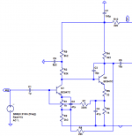
Here is a similar circuit with both RCs implemented (based on the Sansui AU-5900 tone amp stage):Your second recomendation, just so i understand correctly, is to add the resistor-capacitor-ground connection before, or after the R1?
The stock circuit without them has OK PSRR (~55-60 dB), with them it becomes pretty much bombproof (>100 dB of input PSRR from about 50 Hz up).
As long as you install it the right way round...I used 50V 10uf for C7, could that be an issue. And C1 is polar, i assume that's fine?
I am not quite sure what you mean.Could this be the issue:
I have my signal ground, connected to the ground on this circuit, should i leave it off?
The ground of the guitar pickup is already going to the DC ground wire. I believe i tried connecting only the signal on the last preamp build attempt, and the amp and preamp still had major disagreements. i don't want to ruin my amp with these tests.
You will not get around connecting both signal and ground to the input of your preamp. Its output signal and output ground go to the amp input. And your preamp's power supply ground better be floating, i.e. either batteries or an old-fashioned transformer power supply (nothing very big required, 3 VA would be plenty).
Given the partly high impedances, a conductive enclosure centrally connected to ground would be beneficial, even if it's just copper foil taped to a plastic case. (Al foil also works but is harder to make contact with.) It should get a direct connection only in one spot, but ~10 nF capacitors on other inputs and outputs may be beneficial to keep RF out (which is very much necessary, as the junction of a transistor at very low Ic - like the input transistor - is quite nonlinear indeed).
Attachments
Last edited:
yes, my amp circuit has a + and - terminal, + recieves the output wire from the preamp, and - recieves the output ground from the preamp, or am i mistaken?
for the power supply wires, it's an 18V DC switching adaptor, with a white and bare wire. so + and -(ground). I thought the - connects to the ground of the circuit.
All the voltage values from the provided schematic match reality with the bare wire wired like this. but it therefore is also connected to signal ground. i was told to do this when building the first preamp, to connect the second wire from the power supply to signal ground. But so then the circuit has two ground connections, doesn't it? power supply ground, and signal ground, both connected.
I can't get a stable voltage reading right after the output cap. it should be 6.4m, but it jumps around between 5 and 3.2, it's easy to get a stable voltage reading at all the other points.
Connecting only the signal wire from amp to preamp caused regular high pitched popping, and connecting both signal and ground between amp and preamp circuits seems to be worse. i don't want to damage anything. i added an aditional decoupling capacitor before r1.
What could possibly be the issue, everything seems fine before the output caps. Should i just replace the transistors? Adding the recomended 220R resistor between the power supply and the circuit obviously changed all the voltage readings at all the points, so wouldn't that affect the paramters of the circuit? and that didn't give a stable voltage reading after the output cap either. i replaced the 2.2u with the 10u as the schematic originaly asked for, and that didn't change anything.
I don't know how to proceed in solving this. I feel like i'm asking too many questions, but i just can't figure out what's wrong
What is 6.4m?
After the output cap (from this preamplifier) you should have not any DC voltage.
That is the purpose of output capacitor in the single supply amp/preamp, to block the DC voltage.
After the output cap (from this preamplifier) you should have not any DC voltage.
That is the purpose of output capacitor in the single supply amp/preamp, to block the DC voltage.
Nope. Ideally you'll use a 1/4" jack (either TS or TRS with T+R connected) so that you can use ordinary instrument cable. Flying leads are not exactly the very definition of good shielding. That goes for both sides, the input even more so.yes, my amp circuit has a + and - terminal, + recieves the output wire from the preamp, and - recieves the output ground from the preamp, or am i mistaken?
Uh-Oh.for the power supply wires, it's an 18V DC switching adaptor,
You can have an arbitrary amount of "fun" with these.
Make / model / mains plug type or photo?
Does your main amp have a protective earth connection?
I'd suggest getting two 9 V battery clips and batteries and hooking those up in series. This could spare you a lot of grief in this application.
That is correct. The interesting part, however, is: where does the power ground actually go?with a white and bare wire. so + and -(ground). I thought the - connects to the ground of the circuit.
All the voltage values from the provided schematic match reality with the bare wire wired like this. but it therefore is also connected to signal ground. i was told to do this when building the first preamp, to connect the second wire from the power supply to signal ground. But so then the circuit has two ground connections, doesn't it? power supply ground, and signal ground, both connected.
If you connect it to a battery, you can pretty much say "nowhere", disregarding a few pF of capacitive coupling to its surroundings. It is pretty much just a voltage source happily floating in free space, without a care in the world. Your circuit can be at whatever potential it wants and it basically won't matter.
Now, let's be slightly fancier and use a traditional transformer-based power supply. The transformer will have a bit of capacitive coupling between primary and secondary windings (usually in the tens or hundreds of pF, depending on size, and usually one end of the primary more than the other), and the insulation will get unhappy if any potential difference (voltage) exceeds a few kV, but other than that it still does a reasonably good job at floating.
A switch-mode power supply, now that's a real can of worms. These are inherently noisy and absolutely require mains filtering of some sort. Often their mains filter topology is that of a supply whose secondary-side ground is firmly tied to protective earth (PE), like a PC's. (What's called an IEC Class I device.) Let's say 4.7 nF from live (L) and neutral (N) to PE each, plus some series inductors and a common-mode choke if we're feeling luxurious.
How do you transform these into a Class II (floating) supply? Yep, remove the PE connection while leaving everything else as-is. No kidding. Of course that's not terribly ideal, but there's a bunch of countries where having a PE connection still counts as some sort of luxury. Which wouldn't be half as bad if the mains were at least balanced and ground-centered, i.e. (L+N)/2 = 0 V all the time, but nope. (Only a few countries do this, Norway comes to mind.) It's 1 phase + 1 neutral, so (L+N)/2 is half the mains voltage. Now your mains filter wants to capacitively couple to that, via about 10 nF.
The impedance of 10 nF is not very low at 50-60 Hz, but we are still talking substantially more than a typical small transformer. And this is now connected to your preamp's audio ground, and then quite possibly via an audio cable to your amp and to PE within that, a ground path of small but non-zero resistance. If there is some hum induced across the shield resistance of your audio cable, the amp input has no way of knowing that this is not actually part of your signal. And it's not just hum, but also all the other fun stuff the mains filter has taken out, ever more so with increasing frequency. All dumped right into your signal ground connection. Joy.
There are obviously ways of making SMPS less critical, but often you don't have the kind of access to its components that they require. If all you get is L and N in and + and - out, tough luck. You can buy little SMPS units for internal use with a metal case that'll have L, N and PE connections in addition to secondary-side output and ground. This'll have something like a 4.7nF Y-rated capacitor between secondary side ground and PE, and a mains filter with components tied to PE. However, even when mains-side PE is hooked to the PE terminal (which conveniently dumps all the mains filter crap into PE), the secondary side still remains floating unless explicitly hooked up. And whatever capacitive coupling it has is to PE, which some corner of your system is likely to be connected to anyway, so it tends to qualify as "quiet". Certainly nothing with a substantial part of mains voltage over it.
EDIT:
As indicated by the guy before me, you should be seeing just about no DC at all in this spot, and all the AC that your amplifier puts out. If the 5 and 3.2 indicated is in mV then your multimeter probably is reacting to a bit of AC. If it were in V then your output coupling cap would be accidentically reversed or defective - which would no doubt explain the racket.I can't get a stable voltage reading right after the output cap. it should be 6.4m, but it jumps around between 5 and 3.2, it's easy to get a stable voltage reading at all the other points.
Last edited:
Here is a schematic as built in the seventies and simulated (today) it worked for years but there can be hiss if I remember. Values are a little different, distortion is very low and circuit very stable. 😎
which transistors to use for schematic in pic 2 with 13db gain in post #15 ?
Last edited:
- Home
- Source & Line
- Analog Line Level
- What's wrong with this preamp circuit?