Yeah, this is why this thread should have been a continuation of the previous thread started that referenced the specific design
Nice design. LM317 delivers 1.25 V to 50 Ω ballast resistor, essentially independent of VIN, thus turning it into a constant-current source of 25 mA. The pair of valves are in charge of sharing that symmetrically a'tween 'em, resulting in near-perfect push-pull balance. The 10,000 to 150 Ω step-down transformer in turn has a √( 10,000 ÷ 150 ) = 8.16 to 1 ratio (on the 150 Ω tap. 11.5 to 1 on the 75 Ω tap.)
B+ not shown, but I'd assume it is 100 V, given 6DJ8 ( https://frank.pocnet.net/sheets/191/6/6DE4.pdf, midway down) has a 90 VA recommendation. Transconductance is 12,200 µ℧. 12.2 mA/V, translated from oblique units. Pretty sensitive to small input variations!
With a nominal plate dissipation of ²⁵⁄₂ mA × 90 V = 1,100 mW per valve, it is a bit of a pipsqueak, isn't it? Output power … maybe ½ to ⅓ W total? Cool!
Thanks for the diagram.
⋅-=≡ GoatGuy ✓ ≡=-⋅
Yeah, this is why this thread should have been a continuation of the previous thread started that referenced the specific design.
.
Actually, the OP asked a specific question. We could do him the courtesy of answering it rather than go off to display our individual prowess.
Jan
I seem to remember using the LM317 in that manner and finding that its varying impedance with frequency was a little problematic.
I'd run the plate voltage about at maximum to allow for the most possible input voltage.
The O/P needs a very different transformer than the Edcor specified. I suggested a 10K:16 guitar output transformer, even better if it has a 4 and 8 ohm tap on that 16 ohm winding.
I'd run the plate voltage about at maximum to allow for the most possible input voltage.
The O/P needs a very different transformer than the Edcor specified. I suggested a 10K:16 guitar output transformer, even better if it has a 4 and 8 ohm tap on that 16 ohm winding.
That was tube (singular).
You reckon without horns and headphones.
Actually, the OP asked a specific question. We could do him the courtesy of answering it rather than go off to display our individual prowess.
Jan
That’s very encouraging Jan Didden. There’s so many replies that dance dangerously close to my question that I was tempted to just quit this project but I’ve already bought some parts and I’m going to try hard to get my questions answered. I just need to learn to how to better phrase and better language my questions. Hmmm, let me think?
Last edited:
Your question and suggestion was clear enough. But most people do not bother to read the question but reply to and try to trump the last post.
Typical forum behaviour.
Your answer is in post # 16.
Jan
Typical forum behaviour.
Your answer is in post # 16.
Jan
but I’ve already bought some parts
So which parts did you buy?
You have the option of buying different headphones or a different output transformer. You could add some series resistance between the 75 ohm tap and each headphone driver, but you haven't told us which 23 ohm headphones you have.
Eddiegnz1,
Here is an example:
Design a single ended amplifier.
Pick an output tube, lets use a 300B.
The 300B has a plate impedance, rp, of 700 Ohms.
Design an output transformer that will provide a reasonable load, for the 300B, 5X rp.
5X 700 = 3500 Ohms
Make the transformer work with an 8 Ohm speaker.
Root of (3500/8) = 20.9 turns ratio.
Now, I hope the "number" of the turns ratio means something to you now.
Of course for a proper transformer design, you have to know a lot more:
The power output from the output tube (Watts)
The DC quiescent current the output tube will stand (mA)
The number of turns in the primary to get the inductance you need at low frequencies
The Amp x Turns (1000x mA X Turns)
The lowest frequency you want at full power
The amount of laminations needed for the above.
And how to interleave the primary and secondary to get the high frequency response that you want.
Now you see why a lot of people ask what output transformer do I need for my circuit
(I do not want to design and wind my own output transformer).
The amount of the primary impedance in a 300B amp is a tradeoff.
Use a 2500 Ohm primary, and get less power and higher distortion, and a low damping factor.
Use a 3500 Ohm primary, and get medium power and lower distortion, and a medium damping factor.
Use a 7000 Ohm primary, and get much lower power, and lower distortion at that low power, and a high damping factor.
Of course, the DCR of the primary and the DCR of the secondary affect the damping factor, and also affect the insertion loss (power loss within the transformer).
And a 7000 Ohm primary will use more turns, and perhaps smaller wire, and affect damping factor.
Lots of tradeoffs.
I hope all this is helpful to you.
Last edited:
That’s very encouraging Jan Didden. There’s so many replies that dance dangerously close to my question that I was tempted to just quit this project but I’ve already bought some parts and I’m going to try hard to get my questions answered. I just need to learn to how to better phrase and better language my questions. Hmmm, let me think?
I apologize for “contributing to the rabbit-hole” discussion, Eddie. In the end, your “take-aways” should be
№ 1 - transformers are bidirectional devices;
№ 2 - they're remarkably close to perfect, as well;
№ 3 - by convention, one side is called 'primary', the other(s) secondary;
№ 4 - using k = ratio of (primary / secondary) windings…
№ 4a - … VSEC = 1/k • VPRI
№ 4b - … ISEC = k • IPRI
№ 4c - and vice-versa in looking the 'other way' (secondary-to-primary)
№ 5 - any load of R Ω on secondary “looks like” k² R to the primary side
In your original post, your ratio was (k = 5.1) and thus (k² = 5.1² ≈ 26×) as a multiplier. As Jan and others pointed out, whatever load (in Ω) is attached to the secondary “looks like” (k² • that) to the primary. An 23 Ω load, looks like (26 × 23 Ω) ≈ 600 Ω to the tube driving the primary. № 2 - they're remarkably close to perfect, as well;
№ 3 - by convention, one side is called 'primary', the other(s) secondary;
№ 4 - using k = ratio of (primary / secondary) windings…
№ 4a - … VSEC = 1/k • VPRI
№ 4b - … ISEC = k • IPRI
№ 4c - and vice-versa in looking the 'other way' (secondary-to-primary)
№ 5 - any load of R Ω on secondary “looks like” k² R to the primary side
In your post (№ 3), you asked, “so does this mean that you can put 8 Ω or 2000 Ω on secondary, and the primary only shows 600 Ω?” To which the answer was, “no, whatever's on the secondary is multiplied by 26 as far as the primary is concerned.”
There you are, mate.
ZPRI = k² ZSEC … where
k = TPRI / TSEC (turns ratio)
I expect by now that should summarize what-all was discussed before this point by everyone. k = TPRI / TSEC (turns ratio)
⋅-=≡ GoatGuy ✓ ≡=-⋅
the primary winding by convention is the winding that connects to the source of power, and the secondary winding connects to the load...basic knowledge...
the OP seems to be a newbie, and as SY would say, get yourself a copy os Morgan Jones' books and learn from it..
the OP seems to be a newbie, and as SY would say, get yourself a copy os Morgan Jones' books and learn from it..
Team of Archaologists Find Technical Data For 6DJ8
GoatGuy you've answered my question so clearly. Thank you so much. But that leads to the next question
What then is the "Load Resistance" of the 6DJ8 (or ECC88) ? The attached images. That is technical data of a different tube I saw in a youtube video but I've been searching for the same data for the 6DJ8 (or ECC88).
In other words, can I assume that the "load resistance" is the ohms that the tube prefers to see ...in other words, the optimal ohms that I want the primary side of the output transformer to present to the output pins of the tube?
...
№ 5 - any load of R Ω on secondary “looks like” k² R to the primary side[/indent]In your original post, your ratio was (k = 5.1) and thus (k² = 5.1² ≈ 26×) as a multiplier. As Jan and others pointed out, whatever load (in Ω) is attached to the secondary “looks like” (k² • that) to the primary. An 23 Ω load, looks like (26 × 23 Ω) ≈ 600 Ω to the tube driving the primary.
...
GoatGuy you've answered my question so clearly. Thank you so much. But that leads to the next question
What then is the "Load Resistance" of the 6DJ8 (or ECC88) ? The attached images. That is technical data of a different tube I saw in a youtube video but I've been searching for the same data for the 6DJ8 (or ECC88).
In other words, can I assume that the "load resistance" is the ohms that the tube prefers to see ...in other words, the optimal ohms that I want the primary side of the output transformer to present to the output pins of the tube?
Attachments
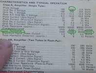
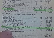
attached is the data sheet which says something about 20,000 ohm
but It looks like the optimal ohms that the tube wants to be presented with depends on the voltage supplied to the tube, right?
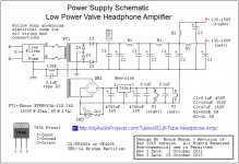
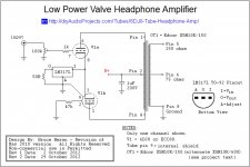
Attached is the schematic which says the tube will be fed 135 to 150 volts. Based on that, what is the ideal ohms rating of the primary of the output transformer?
I know the schematic calls of an output transformer with primary of 10,000R and secondary of 150R but I'm trying to not buy another set of headphones due to budget. I really like my Senheisers anyway. So i'm going to go search for the right output transformers.
but It looks like the optimal ohms that the tube wants to be presented with depends on the voltage supplied to the tube, right?
Attached is the schematic which says the tube will be fed 135 to 150 volts. Based on that, what is the ideal ohms rating of the primary of the output transformer?
I know the schematic calls of an output transformer with primary of 10,000R and secondary of 150R but I'm trying to not buy another set of headphones due to budget. I really like my Senheisers anyway. So i'm going to go search for the right output transformers.
Attachments
For triode at a given operating point, you have mu/amplification factor (volts into the grid gives volts out at the plate), Gm/transconductance(volts into the grid gives current out at the plate), and Rp/plate impedance (internal impedance of the tube).
Ideally a triode is loaded with at least 3x the plate impedance to provide a healthy balance between distortion and power.
The data sheet you posted shows a pentode operating as a pentode, and that's a bit more complicated than loading a triode and not all that applicable to the differential 6DJ8 headphone amp (thankfully!).
rp is 2.6k if Vp is 90 vdc....
so if you are using this tube in single ended, it wants to see 2.6 x 3 or 7.8k of primary impedance...
now, i f you are running push pull class A, then that is 16k primary impedance, and these guidelines are not written in stone...
so if you are using this tube in single ended, it wants to see 2.6 x 3 or 7.8k of primary impedance...
now, i f you are running push pull class A, then that is 16k primary impedance, and these guidelines are not written in stone...
I don't think the answer is in post #16 because 598.23 is the number you get AFTER you multiply by the impedance of the headphone/speaker. So i don't think you multiply by the impedance of the speaker twice. Right?...
Your answer is in post # 16.
Jan
I don't think the answer is in post #16 because 598.23 is the number you get AFTER you multiply by the impedance of the headphone/speaker. So i don't think you multiply by the impedance of the speaker twice. Right?
You are right, I thought that number was the transformer ratio squared. Sorry bout that.
I merely wanted to illustrate, as others have done, that whatever you see t the primary is the secondary impedance times that value.
Jan
the original question has been answered for me. I'm very clear on it now...thank's to y'all. I love forums like this. Thank you ALL.
So then I have three options;
1) add a resistor (177 ohms) after the output transformer. In other words, add a resistor in series with the headphones to increase the load impedance from 23 to 200?
2) return the output transformer to EDCOR and exchange it for one with higher turns ratio? in other words, return the one i bought which has a 5.1 turns ratio in exchange for the one with the highest turns ratio (which is 8.2). That still leaves me needing a resistor but instead of having a 177 ohm resistor i would have a 52 ohm resistor. (or very close to those ohm numbers, 177 or 52)
3) buy...no never mind, i'm definitely not going to buy different headphones
thanks again y'all
I'm guessing he's running a lot higher B+, probably 150-200v. At 90v, there's only 1.3v between the cathode and ground. The LM317 requires a 1.25v drop to even work. In practical terms, it really requires at least 3-5v to account for internal transistor drops and feedback, depending on the in-out voltage difference. The 317 also has an equivalent internal impedance that drops with frequency, so some don't like to use it as a CCS. There are other ways to skin the cat - LM134 works at slightly lower voltages and has a slightly more consistent internal impedance, but has a lower current limit so you need to parallel several. Or several J510s in parallel would work.
Nice design. LM317 delivers 1.25 V to 50 Ω ballast resistor, essentially independent of VIN, thus turning it into a constant-current source of 25 mA. The pair of valves are in charge of sharing that symmetrically a'tween 'em, resulting in near-perfect push-pull balance. The 10,000 to 150 Ω step-down transformer in turn has a √( 10,000 ÷ 150 ) = 8.16 to 1 ratio (on the 150 Ω tap. 11.5 to 1 on the 75 Ω tap.)
B+ not shown, but I'd assume it is 100 V, given 6DJ8 ( https://frank.pocnet.net/sheets/191/6/6DE4.pdf, midway down) has a 90 VA recommendation. Transconductance is 12,200 µ℧. 12.2 mA/V, translated from oblique units. Pretty sensitive to small input variations!
With a nominal plate dissipation of ²⁵⁄₂ mA × 90 V = 1,100 mW per valve, it is a bit of a pipsqueak, isn't it? Output power … maybe ½ to ⅓ W total? Cool!
Thanks for the diagram.
⋅-=≡ GoatGuy ✓ ≡=-⋅
- Home
- Amplifiers
- Tubes / Valves
- What's This Formula Tell You