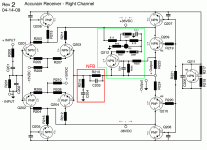
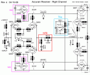
This is the right channel of the Accurain Receiver sold by Radio Shack.
If someone could please take a look and describe the circuit? The amp has
about 15dB of gain without the pre section. It looks like some sort of double LTP.
Thread located here
http://www.diyaudio.com/forums/showthread.php?s=&postid=1802165#post1802165
If someone could please take a look and describe the circuit? The amp has
about 15dB of gain without the pre section. It looks like some sort of double LTP.
Thread located here
http://www.diyaudio.com/forums/showthread.php?s=&postid=1802165#post1802165
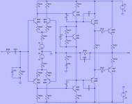
Attachments
Member
Joined 2009
Paid Member
so it does, balanced all the way.
I'll let the gurus describe it, but looks to me like the signal comes in, is fed to two LTPs each one deals with one side of the signal (positive going and negative going waveform) and then a biass circuit and balanced two-stage EF output.
I'll let the gurus describe it, but looks to me like the signal comes in, is fed to two LTPs each one deals with one side of the signal (positive going and negative going waveform) and then a biass circuit and balanced two-stage EF output.
Thank for the quick reply. What are the bias transistors? (Q205,Q206)
More facts:
The amp has no bias current through the output resistors.
I ran the unit into 32 ohms bridged at 100W (56V).
More facts:
The amp has no bias current through the output resistors.
I ran the unit into 32 ohms bridged at 100W (56V).
The left hand side of the circuit is a standard symmetrical LTP and VAS. Q206/205 are the VAS transistors, just drawn upside down. I can't work out what Q207/208 are doing though. They look like a common-base driver for the output stage, but I can't see how they can possibly be biased on.
Symmetrical LTP and VAS. . .that's great. I could have transposed Q207/208 emitter and collector.
Would that make a difference? I'll take a look and retrace.
Q207 - C1027 npn
Q208 - A1023 pnp
Q211 is on the heatsink.
Q212 is fed by more than is shown
Would that make a difference? I'll take a look and retrace.
Q207 - C1027 npn
Q208 - A1023 pnp
Q211 is on the heatsink.
Q212 is fed by more than is shown
The schematic is drawn very oddly but don't let it confuse you... This looks like a very typical amplifier topology with dual differentials feeding a dual VAS. I think you have just drawn the drivers incorrectly and mixed the base and emitter connections. The VBE multiplier should feed the bases and the emitters should feed the resistors of the output transistors. Those capacitors in the drivers are likely also drawn into a wrong place. I suggest you recheck the circuit for drawing errors.
I expect you have, because if you swap them around you pretty much get the circuit that teemuk posted.gni said:...I could have transposed Q207/208 emitter and collector...
It's a Vbe multiplier, so it's on the heatsink to keep it the same temperature as the output devices, for thermal compensation.gni said:...Q211 is on the heatsink...
Q212 is part of the current limiting circuitry. It measures the current through one of the output transistors via the voltage across its emitter resistor.gni said:...Q212 is fed by more than is shown
That you all for the input . . . . sorry about the none standard drawing . . . I drew it
so it had no intersecting lines. . . still looking into the possible swap of c e b parts.
so it had no intersecting lines. . . still looking into the possible swap of c e b parts.
Yes... i think the same.... dead...they have just forgot to buried this one
Inspired into Marshall Leach amplifiers from 1970.
And worse..seems this one has the output stage operating in class B.... tragedy!
I love those old technologies...but not Marshal leach amplifiers..and i hate, in special, double differential.
regards,
Carlos
Inspired into Marshall Leach amplifiers from 1970.
And worse..seems this one has the output stage operating in class B.... tragedy!
I love those old technologies...but not Marshal leach amplifiers..and i hate, in special, double differential.
regards,
Carlos
Attachments
Carlos, you are incorrect on your dates. To my best estimate, Marshal Leach did not write about TIM or amps until 1975. By then GAS, SWTP, SAE, ElectroResearch, etc had produced commercial complementary differential bipolar input power amps.
Class B!
Is that why the amp is cold during idle and sounds harsh?
Remember -- this amp is the Accurain Receiver from RS.
But really the ST&S Corp Rx iSonic 84
"the receiver/amplifier receives the AC Line Audio Transmitter’s signal (4.3MHz to 20.9MHz) through AC power line and converts back to audio signal. The built-in 50-watt audio amplifier enhances sound quality"
http://www.stt.com.tw/product/rx84.html
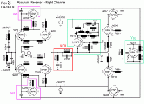
Do you think it is possible to re-bias the amp to Class AB via the Vbe (Q211)?
Is that why the amp is cold during idle and sounds harsh?
Remember -- this amp is the Accurain Receiver from RS.
But really the ST&S Corp Rx iSonic 84
"the receiver/amplifier receives the AC Line Audio Transmitter’s signal (4.3MHz to 20.9MHz) through AC power line and converts back to audio signal. The built-in 50-watt audio amplifier enhances sound quality"
http://www.stt.com.tw/product/rx84.html
Do you think it is possible to re-bias the amp to Class AB via the Vbe (Q211)?
Hi,
before you re-bias anything, measure the voltage across the two output emitter resistors.
While you're at that measure voltages throughout the amplifier. You can use this to estimate what currents each section are operating at.
before you re-bias anything, measure the voltage across the two output emitter resistors.
While you're at that measure voltages throughout the amplifier. You can use this to estimate what currents each section are operating at.
I was just about to start. I already measured the voltage across the emitters and it
was 0 V (or lower than I can measure.
Thank you Andrew. . . probably saved me headaches again.
was 0 V (or lower than I can measure.
Thank you Andrew. . . probably saved me headaches again.
what's the lowest resolution on your AC voltage scales?
you need at least 1mVac from a 2000mVac full scale reading.
Far better is 0.1mVac from a 200.0mVac full scale reading. and the same for DC voltages.
you need at least 1mVac from a 2000mVac full scale reading.
Far better is 0.1mVac from a 200.0mVac full scale reading. and the same for DC voltages.
Thank you John Curl..so..not to blame Marshall Leach
Fine.....now i know the real guilty one(s)
In my country, all amplifiers are this way...all them double complementary into the input.... very low imagination my people has....at least they may match those things.
regards,
Carlos
Fine.....now i know the real guilty one(s)
In my country, all amplifiers are this way...all them double complementary into the input.... very low imagination my people has....at least they may match those things.
regards,
Carlos
Milivolts readed into the power transistors emitter leads
means the ouput is conducting... this show the amplifier is operating in class AB...
No voltage (milivolts DC) measured over the emitter resistances seems the ouput is cutted...this will produce some distortions into low volume levels.... when cutted is operating class B.
One milivolt or less into the emitter resistances is enougth to avoid switching noises...will be less good if you do not find some milivolts there.
Previous stages, for sure..all them... are conducting, and this is made this way to avoid switching noises when amplifier goes from cutted to conduction as the effect of audio entering and producing the conduction.... you know...audio turns the transistor on.
Cutted output transistors can be used into Radio Frequency...because carrier will force them to conduct....but even into radio frequencies they use Class A...well..needs some constant signal above 500 milivolts to force transistor to conduct... audio can do that..but sometimes, into low volume moments, the audio is not enougth to force transistor to be "on"..so..it will be switching between on and off when level is near the threshold of conduction and cut.
Carlos
And here are the measurements:
Andrew -- My meter will measure 0.1mV resolution. RS $70 unit. . . always bben good.
Destroyer X is correct -- the unit is class B . . . there just isn't so much as
a 0.1mV across those emitter resistors. Looks like the rest are 'on' and open
to conducting.
Andrew -- My meter will measure 0.1mV resolution. RS $70 unit. . . always bben good.
Destroyer X is correct -- the unit is class B . . . there just isn't so much as
a 0.1mV across those emitter resistors. Looks like the rest are 'on' and open
to conducting.
Attachments
- Status
- Not open for further replies.
- Home
- Amplifiers
- Solid State
- What's this Amplifier Design