I've just managed to pull apart another broken car amp, and I've pretty much struck gold as I can use the SPMS from it.
Now, I've tested it at different voltages...
12v in = 26v out
13v in = 28v out
14v in = 30v out
15v in = 32v out
16v in = 34v out
I've rounded the values a little but you get the idea...
Now the amp module I want to power (41Hz AMP9) says the max voltage is 26v... So I'm guessing the 30v will be too high for it...
Now, I may try a diode or two on the input to bring the voltage down a little, or even lose a turn on the secondary windings, but I need to know if my car's electrical system is ever going to go over 14v at all?
I've tried searching, and found mixed results, and no definite answers.
I'm tempted to treat 15v as the absolute max....
max voltage car electrical system
MikeHunt79
Times change, but alternators USED to be adjusted to give 13.8 to 14.2V. Significantly hgher voltage is likely to shorten battery and headlights life.
SandyK
MikeHunt79
Times change, but alternators USED to be adjusted to give 13.8 to 14.2V. Significantly hgher voltage is likely to shorten battery and headlights life.
SandyK
Re: max voltage car electrical system
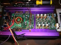
It's big and purple, and says on the front:
MOSFET | AMP-600
AMPLIFIER | 150W X 4CH
| 600W MAX
It looks pretty cheap and nasty, but the rails are pretty ripple free, and the toroid has rather thick cables, meaning it should give a good amount of current...
Anyway, I simply took 1 winding of both of the secondary windings, and now I got 28V at 16v input, and 26v at 15v. This is perfect! 🙂
EDIT: What's the best way of removing enamel from magnet wire?
Ahh, ok... I'll treat 15v as the limit to be on the safe side.sandyK said:MikeHunt79
Times change, but alternators USED to be adjusted to give 13.8 to 14.2V. Significantly hgher voltage is likely to shorten battery and headlights life. My car is 15 years old anyway, so I guess it confirms to the rules. 😀
SandyK
God knows what make it is...Perry Babin said:What make/model amp is it?
You may be able to regulate the power supply to limit it to 26v.
It's big and purple, and says on the front:
MOSFET | AMP-600
AMPLIFIER | 150W X 4CH
| 600W MAX
It looks pretty cheap and nasty, but the rails are pretty ripple free, and the toroid has rather thick cables, meaning it should give a good amount of current...
Anyway, I simply took 1 winding of both of the secondary windings, and now I got 28V at 16v input, and 26v at 15v. This is perfect! 🙂
EDIT: What's the best way of removing enamel from magnet wire?
Hi,
I have measured a lot of vehicle systems' voltages over the years, and 14.6VDC is the highest I can recall seeing on any non-commercial vehicles. This is when charging was taking place, of course, and with a low loading, but most commercial vehicles favour nominal 24V.
Incidentally, many people don't seem to appreciate that a fully-charged nominal 12V car battery should give around 12.6volts minimum, without any concurrent charging taking place (i.e. without the engine running).
Regarding the removing of enamel issue, it depends on the specific application, but I have used 'scraping' with almost anything from a sharp pen-knife, Stanley knife, scalpel etc., or 'abrading' with fine sandpaper, wet & dry, and emery cloth etc. Some enamel is made to simply 'burn off' when heated sufficiently for soldering, without the need for any removal process prior to soldering, so it will depend on what you need to remove the enamel for.
A long while ago, the enamels used could often be removed with certain solvents, but nowadays I have not had any success with anything used in this manner as the varnishes are usually much better made and often epoxy, polyurethane or similar plastics-based materials.
Regards,
Re: Re: max voltage car electrical system
Sandpaper?
MikeHunt79 said:EDIT: What's the best way of removing enamel from magnet wire?
Sandpaper?
Re: Re: Re: max voltage car electrical system
I use something called lavacol, it removers paint and stuff like that from wood or metal, but wire that I've bought today...you only need to heat it over ~150-200C and remove/take off insulation by handCal Weldon said:
Sandpaper?
I used the file on my leatherman in the end... It worked as the wire took the solder, even if it needed lots of it.
That being said, I've truly butchered it!
Before starting to mod it, I knew the amp didn't work, and I didn't know why... Now I think I do....
When measuring the voltage, it was always with no load....
Even after I changed the number of turns on the toroid, the voltage seemed fine.
I then hacksawed off the amp part of the board.
 The voltage seemed spot on.
I then tested it with a tiny load... nothing! The voltage rail just drops to zero! 🙁 If only I tested this before spending hours desoldering and hacksawing....
Anyway, I now have this rather fetching doorstop. 😱 😀
That being said, I've truly butchered it!
Before starting to mod it, I knew the amp didn't work, and I didn't know why... Now I think I do....
When measuring the voltage, it was always with no load....
Even after I changed the number of turns on the toroid, the voltage seemed fine.
I then hacksawed off the amp part of the board.
The voltage seemed spot on.I then tested it with a tiny load... nothing! The voltage rail just drops to zero! 🙁 If only I tested this before spending hours desoldering and hacksawing....
Anyway, I now have this rather fetching doorstop. 😱 😀
Attachments
When you connected it to a load, did the pulses on the center legs of the power supply FETs go to straight DC (no pulses) equal to the B+ voltage?
They stay exactly the same on both sets power supply FETs, squarewave at 14v (B+ voltage) at 27KHz, weather load is connected or now.Perry Babin said:When you connected it to a load, did the pulses on the center legs of the power supply FETs go to straight DC (no pulses) equal to the B+ voltage?
I remeasured the output voltage again tho, it doesn't drop to 0v anymore, it drops to 6v when I connected a small load... 😕 I'm not sure whats causing this, but it probably explains why the amp didn't output anything thru the speakers...
The load I connected was a 24v fan rated at 750mA.
I couldn't really find anything with a lower load...
The secondary may be completely isolated from the primary. When you measure the voltage on the secondary, you need to use the secondary center tap as the reference (black meter lead in sec center tap).
Using the secondary center tap as the reference, do the pulses on the outer legs of the rectifiers maintain the same amplitude when you connect the fan?
Using the secondary center tap as the reference, do the pulses on the outer legs of the rectifiers maintain the same amplitude when you connect the fan?
Damn, I totally forgot about the grounds being isolated... I was using the ground on the input all along. 😱Perry Babin said:The secondary may be completely isolated from the primary. When you measure the voltage on the secondary, you need to use the secondary center tap as the reference (black meter lead in sec center tap).
Using the secondary center tap as the reference, do the pulses on the outer legs of the rectifiers maintain the same amplitude when you connect the fan?
The blob of solder in the middle of the output caps is actually the secondary ground. So I simply wired the fan up to secondary ground instead of the primary ground, and it starting whizzing away at 26v. 🙂
This was definitely a eureka moment for me, thank you! 🙂 I can now get around to squeezing the amp9 into the amp case.
- Status
- Not open for further replies.
- Home
- General Interest
- Car Audio
- Whats the max voltage my cars electrical system will generate?