There have been plenty of technical answers, but I will add something simple. out of the 10 or so tube amps I've built now, most are just clc or clcrc power supplies.
The only times I've had problems w/ hum it turned out to be a ground loop, and not anything to do w/ power supply ripple. (amps varying from preamps to phono amps to power amps 3 to 30 watts.. speakers usually some 96db per watt drivers)
My uneducated self spent a lot of time trying to fix the power supplies in a couple of amps, only to find that was NOT the problem.
.....I like the idea of the regulator or floating ripple reducer using SS. The ripple reducer does have a settling time, much like a damped RC but less droop relative to the ripple reduction.
...
Michael
Thanks very much for the detailed answer. I do like the relative voltage regulator and if I remember correctly one can set the time constant in such a way that it can act as a slow voltage turn on. In this case the dissipation will have to be carefully watched.
Yves
Many thanks for those numbers, that gives a good indication of the effectiveness of your regulator. Simple and effective. If combined with a slow turn on then one could even use solid state rectifiers without doing damage to the tubes (one needs to wait with applying B+ until the tube's filaments have warmed up. guitar amps normally have a "standby" switch which also reduces the filament voltage).
jrenkin
That was exactly my starting point: when is the residual ripple acceptable enough. I think Michael answered that question best.
DualTriode
Only glanced at the book in the library (they had both) and did not see any solution that grabbed my attention. I'll need to get the book and read it more carefully. As indicated before I've been a HAM from way back (gave it up some time ago and took up audio) and I started out in 1968 with tube gear. Know only too well wiring / placement issues but thanks for the reminder. Seperate chassis is not something I want to do, it has its own issues with high voltage connections etc.
wicked1
As mentioned before, if one is using global feedback then hum is reduced by the feedback so without knowing exactly what topology is being used it is hard to know if it will work in another configuration e.g. with a Schade feedback.
Thanks to all
AM
Last edited:
.
.....
I like the idea of the regulator or floating ripple reducer using SS. The ripple reducer does have a settling time, much like a damped RC but less droop relative to the ripple reduction...
Michael
In a certain way this is still a "brute force" approach. In tubecad was an article that used AC fed into the cathode or the grid of the power tube to cancel PSU noise (not necessarily only 100/120Hz).
AM
Attachments
Michael
In a certain way this is still a "brute force" approach. In tubecad was an article that used AC fed into the cathode or the grid of the power tube to cancel PSU noise (not necessarily only 100/120Hz).
AM
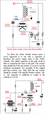
I'm familiar with that approach, and have used it with great success in the Schadeode hybrid design attached.
http://www.diyaudio.com/forums/tube...ar-triode-strapped-pentode-7.html#post2204502
You need to apply the power supply noise more or less equally to cathode and grid, and g2 if it's a pentode, to match the noise on the plate. Since it's the same signal, it doesn't matter what the shape of the noise/ripple waveform is. It's also important to keep any of the injected noise from intermodulating with the signl in the driver.
In the Schadeode circuit, the same PS noise that appears on the plate is injected to the cathode through "ultrapath" capacitor C1, injected to the g2 through zener string D1, and to the control grid through the 100K feedback resistor R1, which works into high impedance. The high impedance of the MOSFET Q1 prevents intermodulation of the noise with the grid drive signal.
Cheers,
Michael
PS the circuit would work as well with a pentode in place of Q1, but would need more voltage, a g2 supply, heaterpower...
Attachments

Last edited:
I'm thinking of building a variation of the "Schadeode circuit", with 6V6 driving a 6CA7... so, a couple of questions: 🙂
Would a pair of 0C3's serve the same function as the diode string?
Does the 6V6 / 6CA7 combo make sense from a gain standpoint?
TIA
Would a pair of 0C3's serve the same function as the diode string?
Does the 6V6 / 6CA7 combo make sense from a gain standpoint?
TIA
MK wrote:
In the Schadeode circuit, the same PS noise that appears on the plate is injected to the cathode through "ultrapath" capacitor C1, injected to the g2 through zener string D1, and to the control grid through the 100K feedback resistor R1, which works into high impedance. The high impedance of the MOSFET Q1 prevents intermodulation of the noise with the grid drive signal.
I'm thinking of building a variation of the "Schadeode circuit", with 6V6 driving a 6CA7... so, a couple of questions: 🙂
Would a pair of 0C3's serve the same function as the diode string?
Does the 6V6 / 6CA7 combo make sense from a gain standpoint?
TIA
I can only answer the OC3 question:
In this schematic the g2 current is less than the minimum amount required by the voltage regulator so it will not work reliably. (Gas voltage regulators need a lot more current than a zener to operate properly.)
AM
Michael
In a certain way this is still a "brute force" approach. In tubecad was an article that used AC fed into the cathode or the grid of the power tube to cancel PSU noise (not necessarily only 100/120Hz).
It works only when the tube is idle. When it works it's transconductance changes, that causes intermodulations between signal and ripples (often is characterized by audiophilitics as lack of details and fuzzy soundstage).
I can only answer the OC3 question:
In this schematic the g2 current is less than the minimum amount required by the voltage regulator so it will not work reliably. (Gas voltage regulators need a lot more current than a zener to operate properly.)
Right, 5 mA minimum. So a resistor to ground will be needed.
The decision to drive 6CA7 by 6V6 is very wise.
Right, 5 mA minimum. So a resistor to ground will be needed.
The decision to drive 6CA7 by 6V6 is very wise.
PS: but I personally would prefer to connect VR tubes between screen grid and cathode, such a way a resistor will limit max current through the screen grid, and dynamic resistance of the screen grid source in respect to cathode would be minimal.
I apologize for 3 messages in row: forum software did not allow me to edit them.
Last edited:
PS: but I personally would prefer to connect VR tubes between screen grid and cathode, such a way a resistor will limit max current through the screen grid, and dynamic resistance of the screen grid source in respect to cathode would be minimal.
I apologize for 3 messages in row: forum software did not allow me to edit them.
Thanks for the response, but I can't visualize your description of how things would be connected between screen and cathode. Also, how would a VR tube interact with the ultrapath cap in Michael's circuit? I thought that VR tubes don't like interacting with capacitance.😕
Thanks for the response, but I can't visualize your description of how things would be connected between screen and cathode. Also, how would a VR tube interact with the ultrapath cap in Michael's circuit? I thought that VR tubes don't like interacting with capacitance.😕
Capacitor when connected in parallel stores the energy. VR tubes ignite on higher voltage than glow after ignited, so current spike discharge the cap below glowing voltage, such a way it starts flashing.
What I propose, is completely different.
2 tubes in series connected between screen and cathode. A resistor from B+ to screen sets the current (40 mA max). No capacitor in parallel with VR tubes, so they are happy.
\\From my HAM radio days I remember that one should not use a capacitor > 0.1 uF across the VR tubes otherwise it becomes an oscillator. Common values used for capacitor were 10nF.Capacitor when connected in parallel stores the energy. VR tubes ignite on higher voltage than glow after ignited, so current spike discharge the cap below glowing voltage, such a way it starts flashing.
.
AM
It works only when the tube is idle. When it works it's transconductance changes, that causes intermodulations between signal and ripples (often is characterized by audiophilitics as lack of details and fuzzy soundstage).
I published FFTs down to -100 db. There is no intermodulation with the ripple because there is no current path between the ripple and signal.
cheers,
Michael
I'm thinking of building a variation of the "Schadeode circuit", with 6V6 driving a 6CA7... so, a couple of questions: 🙂
Would a pair of 0C3's serve the same function as the diode string?
Does the 6V6 / 6CA7 combo make sense from a gain standpoint?
TIA
You could use VR tubes to drop the g2 but would need a CCS or resistor to provide current to keep them lit when plate voltage swings up. The idea of using VR tubes as a shunt regulator has merit also. Either one would inject the correct amount of ripple to g2 for cancelling.
The input tube serves as a V-to-I converter and only needs plate swing equal to the output tube grid swing, so gm is the metric rather than gain. Only a couple of mA/volt is needed so the 6V6 would do the job. A pentode driver would be more linear with a little additional idle current through a separate branch e.g. a plate resistor in addition to the feedback resistor.
6V6 and EL34 is a combo I would like to try. I would run the 6V6 at 100V g2 and the EL34 at 60mA/350V with 250V on g2. For the driver idle point I think somewhere around -5Vg and 16mA would be a start. With a 330 ohm Rk the driver slope would be about 1.8mA/V input. Assuming 2VRMS desired sensitivity, the feedback resistor would want to be about 75K. At 365V P-G the current through the feedback resistor is about 5mA, requiring another 11mA through a plate resistor of about 36K ohms for a total of 16mA. The 6V6 works into about 3K ohms load.
The cathode resistor for the EL34 could be 2K ohms for about 120V on the cathode which would put the grid and 6V6 anode a little over 100V. Some g2 supply will be needed for the 6V6. Looks like B+ would need to be about 500V.
It sounds reasonable. I forgot to add in the fixed plate resistor load to the sensitivity calculation but it's close enough to show feasability.
Cheers,
Michael
Attachments
I published FFTs down to -100 db. There is no intermodulation with the ripple because there is no current path between the ripple and signal.
I understand. They are in different buildings. 😉
I prefer to use additional regulating element that takes care of ripples.
I understand. They are in different buildings. 😉
I prefer to use additional regulating element that takes care of ripples.
Even in Class A the power output tubes vary in anode current when going from low output to high output. g2 is sensitive to the voltage fluctuation and if using a triode for dirver then that triode is sensitive to the voltage fluctuation as well.
I remember the "motorboating" of the cheaper amps if the psu did not have big enough capacitors.
What I am trying to convey is that imho although there is not a "direct" signal path there is however a feedback from the PSU voltage.
AM
The input tube serves as a V-to-I converter and only needs plate swing equal to the output tube grid swing, so gm is the metric rather than gain. Only a couple of mA/volt is needed so the 6V6 would do the job. A pentode driver would be more linear with a little additional idle current through a separate branch e.g. a plate resistor in addition to the feedback resistor.
6V6 and EL34 is a combo I would like to try. I would run the 6V6 at 100V g2 and the EL34 at 60mA/350V with 250V on g2. For the driver idle point I think somewhere around -5Vg and 16mA would be a start. With a 330 ohm Rk the driver slope would be about 1.8mA/V input. Assuming 2VRMS desired sensitivity, the feedback resistor would want to be about 75K. At 365V P-G the current through the feedback resistor is about 5mA, requiring another 11mA through a plate resistor of about 36K ohms for a total of 16mA. The 6V6 works into about 3K ohms load.
The cathode resistor for the EL34 could be 2K ohms for about 120V on the cathode which would put the grid and 6V6 anode a little over 100V. Some g2 supply will be needed for the 6V6. Looks like B+ would need to be about 500V.
It sounds reasonable. I forgot to add in the fixed plate resistor load to the sensitivity calculation but it's close enough to show feasability.
Cheers,
Michael
I'm trying to draw a schematic of the above idea. In the 'Schadeode' but with a 6V6 driver instead of the MOSFET, how would there be a separate feedback resistor from the 6V6's plate resistor? I could see how this is done if the driver plate is RC-coupled to the output tube grid, but how would one have separate plate resistor for the 6V6 and feedback resistor from EL34 plate to grid while keeping the DC-coupling?
Would the input 6V6 have a separate plate and screen voltage supply fed from B+ (before the B+ reaches the OPT primary), while the feedback resistor would go from EL34 plate to 6V6 plate?
The answer is probably blindingly obvious, but I'm just not getting it...
--
Three years after open heart surgery I am having the itch again to build something, cannot sit idle. Am looking at building another SE with the 6BQ5 but this time I'll be using a 5670w / 2c51 / 6N3P-E as driver since both triodes are having a shield between and I have the impression that it is a better tube than a 12AX7 which I used previously. (And I have started to like a lot less feedback than what is happening wiith a 12AX7 and the 5670W is better with an u of 35)
In any case I had the same question on B+ ripple again (I did build a SE with the 6BQ5 about 7 years ago and one speaker had slightly noticeable hum on Fostex FE167E near field, much to my annoyance). In the end I discovered that the triodes in the 12AX7 have slightly different noise figures so there is a recommendation from the manufaturers to use one side as the first one when cascaded.
Getting back to the origin of this thread: In the 6L6GC amplifier that I build back in 2010 I ended up using some OA2 voltage regulators that acted like a zener for a hefty mosfet. Happy enough with the solution although I was not happy with the total weight-to-power ratio and even less with the power-to-valve cost ratio (for replacements).
The little 3.5W UL 6BQ5 that I build 7 years ago was much more to my liking performance wise but this time I aim to build one that does not have an annoying hum when listening near field (about 2 feet) from some 95dB speakers.
Last edited:
- Home
- Amplifiers
- Tubes / Valves
- Whats' the max allowable / reasonable ripple in SE amp?