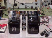
This is a MC-30 "Mac" that I was testing.
Completly different kind of fun, or torture.....
These beasts don't have a lot of Poop, but those big hunks of iron help them kick out a great Round-Tone bass into a good 12" or 15" driver.
I have a Fisher 90-R tuner and a Eico tracer that has been a godsend as being able to listen to gear is a good way to "see" what is going on inside all those parts...
I listen with a 1960's Wharfdale and I use a 360 Simpson as well as a digital to snoop with...
"They made 'em with analog so I look at 'em that way!😎
Attachments
Member
Joined 2002
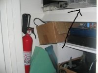
HIPCHECK said:the oh s**t fire safety device
This picture that you have attached with the fire extinguisher with the heat sink, i have this exact same one 🙂 weird 😀
Attachments
i ahve 2 of these, they came from a vertical mount battery charger. reminded me of old aleph amps i am making a mini XSOZ for headphones i think....... lots of junk, and lots more future projects
i have become an junkie
i have become an junkie
Member
Joined 2002
i have a understanding wife, which im lucky!
but id have a hard time explaining me "importing" some more "junk"! 😉
especially when i always lug something home from the local junkyard weekly! im sure im not the only guy who has this situation, LOL
but id have a hard time explaining me "importing" some more "junk"! 😉
especially when i always lug something home from the local junkyard weekly! im sure im not the only guy who has this situation, LOL
Member
Joined 2002
HIPCHECK said:i have a understanding wife, which im lucky!
but id have a hard time explaining me "importing" some more "junk"! 😉
especially when i always lug something home from the local junkyard weekly! im sure im not the only guy who has this situation, LOL
OH OH pick me for that quote 🙂 well i have also heard it lots from my moms mouth towards me and my dad 😛
OK what have you dragged home now 😛 lol
Jase
Currently I have my first working PIC on my desk....
Actulay went to bed last night watching the LEDs danceing around... slept like a log..normaly I keep dreaming about whatever I'm busy with...
It feels so good, but I guess those of you who made the LEDs go on and off were just as impressed with themselves...
Actulay went to bed last night watching the LEDs danceing around... slept like a log..normaly I keep dreaming about whatever I'm busy with...
It feels so good, but I guess those of you who made the LEDs go on and off were just as impressed with themselves...
Sorry, had to share again
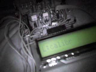
Today working LCD, in working Inductance and capacitor meter...
Still waiting for hightollerance caps from the UK to use a reference, but it should have roughly 5% accuracy now
Today working LCD, in working Inductance and capacitor meter...
Still waiting for hightollerance caps from the UK to use a reference, but it should have roughly 5% accuracy now
Nordic said:Sorry, had to share again
Today working LCD, in working Inductance and capacitor meter...
Still waiting for hightollerance caps from the UK to use a reference, but it should have roughly 5% accuracy now
If you are in one of the larger cities in SA it shouldn't be difficult to talk your way into the physics lab of a university and use a bridge to measure an inductor and capacitor for use as standards --
Good idea... yeah, I'm probably as well of as you can be situated... have a number of technicons (tertiary institions you go to after grade 12) and of course universities in the vicinity...
Cape Town is very metropolitan indeed.
I am so impressed with myself... just finished boxing the unit, and it still works 🙂.
Using your method I should be able to use a better quality cap like a Mica and then knowing to a great accuracy what it is, if I use that it will be even better... still I'm mighty impressed and it was a reasonably easy first pic project... now I'm ready to move on to your atenuators etc...
BTW... how do yuo like my handdrawn PCB from the bit you can see... ran out of photoresist...
Nordic said:
BTW... how do yuo like my handdrawn PCB from the bit you can see... ran out of photoresist...
Have you tried the PIC12F675?
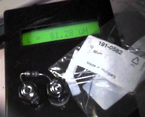
Hi Jack no, so far I only have 16f84a adn 16f627 on my desk... trying to get my head around the A/D stuff of the 627 then I'll look at more advanced pics...
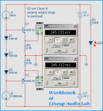
my workbench Push-Pull
hi
I keep on with my virtual electronic workbench.
Must have been done 4-6 different DC buffer preamps
and maybe 30-40 versions of those,
since last I posted in this thread my capture of my current circuit.
Some are not good enough to post at forum,
some were really impossible to get stable in capactive loads, and
a few ARE TOO GOOD to give away publically ...
This one posted is a very powerful preamp output stage,
using only small signal transistors ( <1 Watt ).
Should be able to put out 80 mA true Class A with good results.
I created this first to test 2 new transistor spice models downloaded from Philips.
As you can see these models work close to perfection!
... at least in the virtual world
lineup 😎 research goes on to find the perfect DC-in DC-out buffer
Attachments
Nordic said:At what voltage does that one start to clip?
It will depend on what kind of driver stage / CCS you use.
And of course what is your load impedance.
I dont think +-12.0 Volt peak into 200 Ohm will be any problem at all.
Some of these DC buffers I have built virtually 😀 using 1.66 Volt RED LED for current source,
will not start clip until beyond 2 volt from supply,
when there is enough current to feed the load.
If you use such small signal transistors that are made for higher currents,
like BC337 - BC327 ( 0.8watt ) or BC639 - BC640 ( 1watt )
they wont saturate until Volt C-E is something like 0.5.
The really heavy current pair is BC368 + BC369:
TO92
1 Watt
2 Ampere! = 2.000 mA
40 MHz
hFE 85-375
The only drawback with this pair is MAX 20 Volt,
which means +-10 Volt supply .. maybe could be used at +-12 Volt
if not overdriven.
http://www.elfa.se/elfa-bin/dyndok.pl?vat=0&dok=2412.htm
lineup 🙂
First Snow winter 2006-07
hi
time for me to put on some winter clothes
first snow came this night and it is still falling
wont be long until christmas now
image shows view from Lineup Audio Lab kitchen window
less than an hour ago
lineup 😉 will put his bike into archive until spring comes back
hi
time for me to put on some winter clothes
first snow came this night and it is still falling
wont be long until christmas now
image shows view from Lineup Audio Lab kitchen window
less than an hour ago
lineup 😉 will put his bike into archive until spring comes back
Attachments

I still have to see real snow.... oh well maybe someday....
On this side of the globe, it is now summer... last night was the first night I could almost not sleep because of the heat....
On this side of the globe, it is now summer... last night was the first night I could almost not sleep because of the heat....
Aah c'mon. You Cape Townians hardly get heat like us up in Jo'burg 😀 😀 We've had a terrible heat wave the last couple of days.
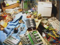
lineup workbench with recycling stuff
🙂
I have so many stuff at my workbench
looks like no particular order at all
but I have a slight idea where this and that part may be found.
Those 2 cards and the heatsink, I got for a few penny.
At the local recycling station with a shop for second hand stuff.
They had a big container full of PCB cards with components.
They were to be desoldered by their workers.
I tried to find those with most transistors on.
Those four TO3 at heatsink are IRF532. I have two of them heatsinks.
Makes 8 of those high voltage ? HEXFETS.
At the card down to the left, you can see a row of 16 pieces of 2N4092 N-JFET. In TO18 capsule.
Next to them is a row of 8 JFET op-amps: LF355H
I do not know and have not decided what to do
with these old, but nice old components.
The work to remove, desolder such PCB cards is not really fun.
Yet, I have spent many hours doing this, before.
Regards
lineup 🙂 directly from his workbench
Attachments
 ...
... - Home
- Design & Build
- Equipment & Tools
- What's on your workbench???