

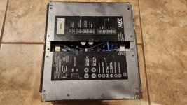
Friend of mine dropped this car amplifier. According to him one channel sounds muffled. I have not got very far, only hooking up 12Vdc regulated supply to it. Without any speakers i measure similar dc on both channels. One thing i noticed that there is discrepancy between legend on the cover and actual speaker wiring.
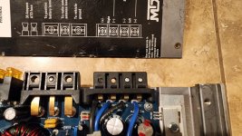
Please see pic. According to cover, grounds are in the middle, live wires flanking.
But inside the amp has alternative live/ground arrangement.
I measured (with amp turned off) connectivity, those two black wires for speaker ground are connected.
It seems to me that amp may be ok, just when he plugs it into crossover which shares ground between channels, it will not work properly.
When separate wires goes to speakers, it may work, but one will be out of phase. But in the car with multiway speakers with common ground for crossover, this will not work.
How is this possible?
Attachments
It looks like they wanted to make it straightforward to use the amp in bridge mode, so inverted one channel. Stuck with that decision then they stipulated that the stereo outputs are "floating" and need wiring without any "common" element. By flipping the +.- designation on the inverted output, the independently stereo wired speakers end up in phase.How is this possible?
Your friend is stuck until he fully isolates his L/R crossover elements. No wonder he gave it to you to figure out! Tricky-tricky...
Yup, just like in many classD amps, avoid connecting grounds together.
This is not classD though.
You are right, that's whats going on. Amp works fine as long as speakers do not share ground.
This is not classD though.
You are right, that's whats going on. Amp works fine as long as speakers do not share ground.
This has been done for years where they will invert one channel mostly to draw even current from the supply capacitors, My guess would be 1985 or so for the fist time it was seen on a product.
Also means you can easily bridge the amplifier as long as you use the right speaker terminals.
Also means you can easily bridge the amplifier as long as you use the right speaker terminals.
Or, the support call costs was adding up, as customers are too often unable to find and throw a switch to put it into "bridge mode". So engineering was called upon to eliminate both problems; the switch and the calls.to draw even current from the supply capacitors,
I bet one channel did sound muffed. Ooof said that channel - some sound still came out due to the voltage drop across the ground wires!Amp works fine as long as speakers do not share ground.
Generally not a good idea to share ground on speakers as the stereo separation might be compromised and that affects imaging also the return wire needs to handle the current and using one will bottleneck it - even without the BTL issue.
Long time ago, when i was building this amplifier with j200/k1529, i learned new thing. Output of the amplifier is grounded...
See here the discussion.
https://www.diyaudio.com/community/threads/amp-out-grounded-power-supply-as-output-why.347506/
See here the discussion.
https://www.diyaudio.com/community/threads/amp-out-grounded-power-supply-as-output-why.347506/
For many of you car amplifier with one channel inverted is nothing new, but for me this was a surprise, as i do not work on car audio stuff...i consider that waste of time. This surely upsets some, but why would you build perfect hifi and listen to it with lawn mover running behind you ears.
AN39, just like wolverine, vfet, or any other amp, unless build as two separate monoblocks, always share ground between left and right channel. Because ground for both channels is common ground of power supply.Generally not a good idea to share ground on speakers as the stereo separation might be compromised and that affects imaging also the return wire needs to handle the current and using one will bottleneck it - even without the BTL issue.
None of these amplifiers suffer stereo imaging.
Its perfectly safe to connect grounds.
Last edited:
You are clearly misunderstanding the issue here.Generally not a good idea to share ground on speakers as the stereo separation might be compromised and that affects imaging also the return wire needs to handle the current and using one will bottleneck it - even without the BTL issue.
Are you saying we all should just be building amplifiers with one inverted channel?
The only amplifiers i recall i built and can not connect grounds are son of zen balanced power amp, and couple f1j, which is same circuit, just more advanced with current sources. Still there is no ground since its balanced.
All other amps, especially chipamps, they all share the ground. Yet they do not suffer stereo imaging.
All other amps, especially chipamps, they all share the ground. Yet they do not suffer stereo imaging.
Ok, i am almost done...i wanted to measure that car amp, you know, using rew or rightmark with soundcard, i do not think i can. Soundcard automatically connects left and right grounds together. What a pain this is.
Maybe I was… I was thinking of the speaker output wires from amps. I never use a common negative speaker cable out to two speakers. Dual monoblock amps have better stereo separation.You are clearly misunderstanding the issue here.
Are you saying we all should just be building amplifiers with one inverted channel?
I got more details from friend. This amp is for his boat, small fishing vessel. I gues this, and crossover goes under dash. He has short wires from amp to crossover, then separate wires to tweeters and woofers. The crossover inside must have common ground. That's an issue. It would not be, if this amp would not have this inverted channel.
Anyway, i offered to rebuild the crossover.
Anyway, i offered to rebuild the crossover.
Makes you wonder if there's an easy way to flip the signal phase of the one inverted channel - like jump around an extra op-amp in there... I wouldnt count on it; stuff as-designed rarely makes it "easy" to undo.Anyway, i offered to rebuild the crossover.
Trust me, if i had schematics, that would be first thing i would do. Likely just jumper wire and some traces cut off would do. But i would likely have to flip the board and undo all the transistors on heasink, which is a lot of work. Great suggestion though.
I haven’t been on the bench much lately. But finally getting to test the Vera-Fi Audio Snub Station Zero (SSZ). SSZ is a unique power conditioning product that provides DC blocker for the mains, an automatic solid state relay Soft Start circuit, and a high performance EMI filter.
I am very excited about the automatic soft start because it allows one to install this product upstream of an amp that uses large linear transformers. If you have ever heard a transient mechanical buzz or “burp” coming from your amp when you first switch it on, that’s the mechanical sound of the copper windings getting mechanically stretched when the 20x higher than nominal current rushes in to magnetically charge the large ferrite core. This stress stretches the copper windings and with enough cycles, can break the copper trafo winding wires and fail.
SSZ uses a precision Hall effect current sensor to monitor current flow real time. The current flows through two NTCs to limit the in-rush. When the current demand is sensed, the NTCs are bypassed about 6 seconds later - allowing the trafo to slowly charge up.
Here is the pre-production proto under test. There were some minor issues which we caught and fixed for the final product. But it’s working very well.

I connected this to a large commercial Class AB amp that has dual 400VA toroidal trafos. This amp makes a large burp sound when switched on and triggers a brownout warning on the power distribution panel. With the SSZ in place, turn on is absolutely quiet and smooth.
There are two outlets (not shown connected) that do not have soft start feature for smaller components like preamps and DACs. However, the DC blocker and EMI filter are still provided and for the smaller outlets, premium German made Schaffner EMI filter modules are used. Quality premium name brand parts are used throughout, including 22,000uF EPCOS electrolytic caps and Wima film caps.
I am very excited about the automatic soft start because it allows one to install this product upstream of an amp that uses large linear transformers. If you have ever heard a transient mechanical buzz or “burp” coming from your amp when you first switch it on, that’s the mechanical sound of the copper windings getting mechanically stretched when the 20x higher than nominal current rushes in to magnetically charge the large ferrite core. This stress stretches the copper windings and with enough cycles, can break the copper trafo winding wires and fail.
SSZ uses a precision Hall effect current sensor to monitor current flow real time. The current flows through two NTCs to limit the in-rush. When the current demand is sensed, the NTCs are bypassed about 6 seconds later - allowing the trafo to slowly charge up.
Here is the pre-production proto under test. There were some minor issues which we caught and fixed for the final product. But it’s working very well.
I connected this to a large commercial Class AB amp that has dual 400VA toroidal trafos. This amp makes a large burp sound when switched on and triggers a brownout warning on the power distribution panel. With the SSZ in place, turn on is absolutely quiet and smooth.
There are two outlets (not shown connected) that do not have soft start feature for smaller components like preamps and DACs. However, the DC blocker and EMI filter are still provided and for the smaller outlets, premium German made Schaffner EMI filter modules are used. Quality premium name brand parts are used throughout, including 22,000uF EPCOS electrolytic caps and Wima film caps.