They are running about 320V.Hi Kodabmx, what voltage for Triode ?
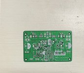
It’s always the small stuff that results to a train length of issue / traffic.I found the problem. A small solder bridge on the bottom side of the board. It unbalanced the LTP input stage. Cleaned it up and it’s all fine now. Playing in stereo with dual monoblocks in same chassis.
View attachment 1131019
Very hopeful it’s singing nicely - like how Eevblog says Bobs’s your uncle in a funny way.
Shall be assembling the circlophone PCB I did few weeks back, still awaiting parts from farnell / element 14.
I think I should have done a window like you have above the power device.
There are some changes so mostly rev2 in the moding. Relocating some components removing something and rev3 is going to be all on one board stereo.
I think I should have done a window like you have above the power device.
There are some changes so mostly rev2 in the moding. Relocating some components removing something and rev3 is going to be all on one board stereo.
Attachments

Onset of attack seems great, midrange is compelling, don't know if I'm correct in feeling there's a bit too much brightness. How's the profile? Is H2 predominant?
The brightness is the compression driver tweeter of the JBL 530. I have padded it by -3dB in the treble. Probably standing a bit too close because I had no room to back up farther. It’s not a bad speaker if you are 2.5m away.
I should go and grab my Vanguards.
I should go and grab my Vanguards.
Here you go, same track but with prototype Vanguards - first song.
Second song but with Vanguards
This is kind of interesting and reminds me of the fullrange driver blind tests I used to do on DIYA.
Let me know what you think.
Second song but with Vanguards
This is kind of interesting and reminds me of the fullrange driver blind tests I used to do on DIYA.
Let me know what you think.
It’s like the Alpha Nirvana which is dominant H2 and less H3 and monotonically descending higher orders.Onset of attack seems great, midrange is compelling, don't know if I'm correct in feeling there's a bit too much brightness. How's the profile? Is H2 predominant?
This is 4W into 10ohms:
This is 12W into 10ohms:
The brightness is the compression driver tweeter of the JBL 530. I have padded it by -3dB in the treble. Probably standing a bit too close because I had no room to back up farther. It’s not a bad speaker if you are 2.5m away.
I should go and grab my Vanguards.
I have the JBL Studio 530's in my home theater. They are a little bright with music, but perfectly fine for home theater duty where clarity in dialogue is a necessity. Could be the Marantz AVR amps are a factor. We will see when I get my Neurochrome amps completed. It does take some distance for the compression tweeter and woofer to come together into a cohesive soundstage. These do not make a good nearfield speaker.
I got my SE MOSFET amp's heatsink to hit 110°C (normally it's only 87°C)... 57°C is cold to me.
Nice, I did think H3 was too pronounced, hence the perceived extra brightness. This said, from here it's hard to say convincingly as it could be the source material and/or YT compression too.
On the bench tonight is a new soft start board called the SFP Plus (v2.2) based on the SFP but with remote main power on and off control with a triac. Design by Jhofland has been tested out by Vunce and works superbly. I want to use it in the A40 amp since I need to have two thermostat switches shut the amp down if the heatsinks go higher than 80C. Standby/On control is through a SPDT momentary push button or toggle switch carrying low voltage (5v), plus two LEDs indicating standby or on. A force off (with latch) is also available for a N/O safety switch such as a thermostat or other switch that shorts out when active. Finally, an open collector output that is designed to control the logic of the RTR SSR speaker protect boards.


Any idea if/when it might be available on your etsy store? I have a board from china with similar features, but it uses relays, and of course doesn't have the open collector logic for your SSR boards. Yours is probably a bit smaller too. If I follow the schematic correctly, looks like there's no more jumper for controlling delay and it's set for ~2sec?
Yes, I’ll make these available in my store soon, now that I assembled it and know it works well. Just tested it and the thermal shutoff switch works well. The delay is closer to 3 seconds. I think it’s controlled by R16 and C5.

Here is a video showing it in action. I didn’t show the fact that I checked the output terminals to verify that the 120vac indeed turns on. Note that the triac remains on but the MOSFETs are low RDson so the current will flow through them preferentially, thus bypassing the NTC’s.
This board is mostly tiny little 0603 chip resistors and all the IC’s are SMT. It’s not a hard build, but probably not for an SMT beginner. I would recommend solder paste and hot plate or hot air as the smaller logic chips have very tight pin spacing. If you can assemble the BTSB Panel Mount, you can definitely do this one.
That's perfect, everything I could want. I've managed to solder 40-50 SOIC-8's without any bridges, I could probably pull it off, plus it might be the nudge I need to buy a hot plate or hot air setup for SMD soldering.
What are the hole dimensions? Same as the SFP for drop in replacement?
What are the hole dimensions? Same as the SFP for drop in replacement?
Quick test - it works in the amp and now playing music. I got myself an extra volt in the PSU rail since no NTC drop out with the MOSFETs bypassing the NTC after 3 seconds of soft start duration. I’ll need to drop the voltage on the final version for production as it’s just running too hot at +30.5v now. OTOH, it’s a solid 50w Class A amp now. 🙂

Board mounting holes are 76mm x 66mm. It’s actually a tad smaller than standard SFP since SMT parts are used.
Board mounting holes are 76mm x 66mm. It’s actually a tad smaller than standard SFP since SMT parts are used.
Last edited:
I just had a thought, if I have +/-30.5v rails, this amp can put out 50W into 8ohms. Increasing the chassis depth to 350mm should drop the operating temp of the heatsink down to about 51C and we now have ourselves an XSA Labs Series One A50 amp! This would also have the benefit of making it a bit roomier and easier to work on inside and increase space between amp board and trafos which may reduce EMI noise pickup.