First thing on the bench on 2022 is the Qubit hybrid 6N6P Class A headphone amplifier. Sounding glorious. 48c DCDC power supply and 6.3v PSU with 700mA filament current.


that’s some killer bass and transient attack!
that’s some killer bass and transient attack!
Great way to start the Year.
I have on the bench a little brother to this, with currently a 12AU7 equivalent in an unconventional configuration - actually I made a mistake and it gave this excellent sound but with low level hiss and crackle - and a single MOSFET biased in Class A via the heater, one channel to play with.
Happy New Year, everyone.
I finally mounted the Qubit headphone amp on a plank. It’s much more user friendly now. This is a purely development proof of concept board. The production one will look very different.

From the Virtual Bench tonight, this is about reducing distortions, still on the simple Tube Hybrid channel. Impedance profile is also flattened till way down there.
There's no way I'll be getting these in the real implementation, but it's indicative of a relative change. My devices won't cut it so there should be an order to Digikey for some new ones to test this in the build. I might still try with what I have at hand as it's fun. There are some additional circuitry I'd need to add and make variable for best results.
It's been tricky getting there: earlier I copied a sub-circuit from a previous sim, totally forgot to copy over the power rails, and was puzzled for more than half an hour about why the sim wouldn't converge at all.
In both circuits, there is a spike above 100MHz, below the hearing threshold though and definitely out of hearing range but hopefully this doesn't affect any other device. I don't think it's going to be a big issue for such a simple circuit.
I haven't added my clean PSU to this build nor to this sim. I expect even better results than currently on the breadboard.
Attachments
It's not ready yet as this is a rabbit hole for me and I'm still doing research/learning so there's a good chance I messed up in the second sim, but here are two things I got inspiration from:
1. Tube Hybrid. Mine is a single channel of this on the breadboard, wired unconventionally (i.e. with my mistake + hiss and crackle but excellent sound). The sim contains a more conventional wiring of this and a resistor instead of the heater linked to the MOSFET stage as I really don't want to use an LM317 for this.
The sim contains a tube model from Duncan amps, no special model for the MOSFET (maybe I should use one?).
2. Check the sim file that Zintolo graciously shared here for feedback. Here again, mine differs a bit from this.
Last edited:
I just assembled three more LD1014D JFETs onto aluminum PCBs with 100R snubber resistor and 3 pin headers. Hot air on top and hot plate in the bottom as usual. These are representative samples from 600 JFETs that I have that will get professionally assembled and tested and matched for a commercial 100w Class A amp. I need 100 matched pairs. 🙂

quick check with cheap tester confirms solder joints are good as it shows N JFET.

quick check with cheap tester confirms solder joints are good as it shows N JFET.
You are one bussy guy X! 100 matched pairs...is this because of dc offset? Or gain, or else?
I normaly do just Idss and Vpinchoff.
I normaly do just Idss and Vpinchoff.
I have - lot of help - I can’t do this by myself. 🙂
Matched so that DC offset is low since it’s a balanced amp. And to make sure the amps all have a similar sound signature. As it is a production amp we want a uniform sound.
Matched so that DC offset is low since it’s a balanced amp. And to make sure the amps all have a similar sound signature. As it is a production amp we want a uniform sound.
I assume the center pin on the Jfet is clipped because the back is soldered to the board. Is this mostly to get more even contact on the G and S contacts? Also, using the tester, is the confirmation that the unit is behaving as an N JFET the primary information with the other measurements being less or not relevant for this test? I've done four boards, three test good and I think the fourth was overheated. Plenty more to do. thanks
These are actually the SMT variant LD1014D so the pins are clipped and pre-bent for surface mounting. TO252 DPAK doesn’t have center pin and uses back pad for pin 2 (you can see what they look like in the tape roll in the photo above). We are having a pick and place machine make 600 of them. This allows them to have proper thermal contact and electrical contact for the testing to match parameters. We also have 1200 MOSFETs to match for the triplets needed for the cascode. At least those are already on a TO247 package.
On the Bench tonight, just a little more tinkering with the Behringer UMC202HD audio interface, of which I am convinced I bought a second-hand dud. I've taken the soundcard and the laptop and I'm on the couch with a loopback configuration, listening to an old CD by Kon Kan - Syntonic. Very rare stuff.
There's always 24k and 48k spikes. I might try again with another cable, TRS this time.
There are some cool folks who did some investigations and found some nice enhancements, including one I was looking for: a Direct IN.
This card might be an exercise in troubleshooting.
At least with the manufacturer driver install I can set ASIO more reliably.
Attachments
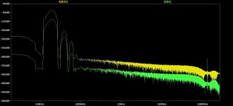
Another little test today with sweeping the frequency and with the Behringer drivers and a TRS cable by Hosa. See those glitches at 24k and 48k - they're the vertical yellow lines?

I don't know what could cause this, so it's not too worthwhile to do modifications if these remain.
I don't know what could cause this, so it's not too worthwhile to do modifications if these remain.
Those glitches are the DAC sample rate clock frequencies. I wouldn’t worry about them. Most drivers don’t even have a response up there (except premium ribbons).
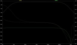
Speaking g of ribbons. I’m working on a new XO for the 6.5in aluminum cone woofer and ribbon tweeter.

crossover is about 3kHz. Working on the voicing now:

I may flip the speaker upside down and try making a Harsch XO to get it time aligned. That would let me use a 4th order on the woofer to drop the 6kHz breakup peak.
Speaking g of ribbons. I’m working on a new XO for the 6.5in aluminum cone woofer and ribbon tweeter.
crossover is about 3kHz. Working on the voicing now:
I may flip the speaker upside down and try making a Harsch XO to get it time aligned. That would let me use a 4th order on the woofer to drop the 6kHz breakup peak.
I am not measuring drivers this time though, just the loopback and then later the hybrid amp. The distortion levels are also abnormally high - you can actually see the trace becoming dirtier as from 4k or so in the graph above. Someone mentioned it might be a buffer issue, so I'll give this a try again tonight.
It does look like I'm going to open this soundcard again and try some scoping internally. It may or may not be helpful to isolate the Phantom power properly as the booster for it isn't actually turned off when the internal switch is set to off, as found by a deeper investigation by another member.
It is interesting in lots of ways for sure: mixed board and noise but it's side-tracking me a bit from the hybrid amp and the tube preamp.
Your XO work reminds me I still have a lot of work to do on that: one for the custom MOSFET subwoofer amp, and some small drivers I salvaged from a Sony boombox. I'll have to re-check how many there are but it's at least a two-way plus a sub driver.
I saved two pairs of complementary Toshiba BJTs from it as well. It was the dirtiest boombox ever, most probably someone working in the construction company used that to accompany his work - lots of white dust inside. I still have to clean the drivers. They have yellow cones. I intend to mount them open-baffle for the stereo field.
More tweaking on the voicing of the XO. I moved it to 3.5kHz now and I think that sounds better.

Pretty amazing how a 500ohm (5x 100ohm 1W metal thin film resistors in series) in parallel across the first big inductor makes a big difference in the phase matching at the XO point.
Here is a candle leak check of the TL. After fixing leaks I used candle to see how much air the TL moves at 31Hz.
Pretty amazing how a 500ohm (5x 100ohm 1W metal thin film resistors in series) in parallel across the first big inductor makes a big difference in the phase matching at the XO point.
Here is a candle leak check of the TL. After fixing leaks I used candle to see how much air the TL moves at 31Hz.
Testing out some NOS (from 1970’s) Russian “Rocket” tubes on Hyperdrive-2. I meant to get 6N1P but accidentally ordered 6N2P.


They work and give a very sweet higher second harmonic profile vs E88CC. Here is 0.355vrms (1.00Vpp) preamp output on E88CC for 0.0023%THD:

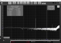
Here’s the 6N2P at 0.15% THD:

Not bad sounding at all. You can see it has a slightly elevated noise floor but still very quiet. Very pleasant sounding.
They work and give a very sweet higher second harmonic profile vs E88CC. Here is 0.355vrms (1.00Vpp) preamp output on E88CC for 0.0023%THD:
Here’s the 6N2P at 0.15% THD:
Not bad sounding at all. You can see it has a slightly elevated noise floor but still very quiet. Very pleasant sounding.