For the love of God, just resell the power transformers and buy new ones with higher voltage secondaries.
I'm sorry this thread has bothered you. I was trying to make use of what I had and thought there might be a simple solution. A couple of folks have put a fair amount of time working on solutions and do I thought I'd explore those rather than throw money at the problem. You know - DIY.
You interested in the transformers?
You interested in the transformers?
Not bothering me. Should have written a little more to make it obvious that this wasn't me crying out in anguish. But now I am a little worried as you still think an additional 4-6 caps + circuitry in that chassis is a "simple solution" so that you can get 20-30 more volts?
Not interested in the transformers. Someone probably would be. It's --by far--the simplest solution here.
Not interested in the transformers. Someone probably would be. It's --by far--the simplest solution here.

WntrMute, i will post the schematic as soon as i can get on my pc to draw it out, by tomorrow i hope.
In the past existed graphical diagrams for these situations, when transformer does not have enough voltage - how much more could be gotten.
WntrMute2 i have found "Conversion Factor Nomogram" but i also made a mistake - it is a nomogram to work out optimum values for the tubes in output stage from a lower voltage PSU regarding the applicaton data recommended for output stage tubes.
It is pretty complicated and i don't have english translation, however i'll post it - maybe someone with more knowledge can do something with it.
( Horizontal dashed lines are an example for calculating 6L6 PP class A output stage from 200 Vdc PSU voltage which should originally work with 250 Vdc ).
Not what You really need, i'm sorry.
Attachments
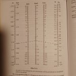
Basically as i understood it - this is nomogram to change working conditions of output stage for lower PSU voltage.
Converson "factor" should be between 0,7 - 2.
The text is too complicated for me to translate it properlly.
I am really sorry beacuse it's my mistake - not what You need.
Converson "factor" should be between 0,7 - 2.
The text is too complicated for me to translate it properlly.
I am really sorry beacuse it's my mistake - not what You need.
WntrMute, I would now have the circuit diagram of your amp with the quadrupler, but I could only export it as a wmf file and this seems not an allowed extension here. Bit late now, will look into it tomorrow
The bias circuit has to be rewired according to the diagram i made, amp, quadrupler, bias cicuit, it is all there.
I hoped you would have recognized that as well, as bias circuit wireing differecies between your original circuit and mine.
Functionally, the difference to the original fullwave is that the quadrupler is halfwave to keep part count down
(fullwave multiplier with only 7Vp avaiable is possibly, but considering the high part count and diode losses not really an option in your case)
Halfwave rectified bias is practically just as good as fullwave, there is nothing that could affect your amp negatively, clean 12Vdc in both cases.
If you want to keep the original bias as is, the only option is to add the10VA transformer , see attachement
Attachments
Last edited:
Looks like the lower part of the bmp got mangled, connecting dots and the 1k resistor is missing, i will correct that and repost, later
- Home
- Amplifiers
- Power Supplies
- What's Going On Here?