LCLC circuits in PSUD2 need a lot of extra damping (compared to RCRC, LCRC, CLC, etc) before they exhibit controlled behavior. Does that mirror reality? I don't know enough to say, but I assume it's somewhat accurate. As accurate as other aspects of the program. Maybe someone could model this in LT Spice and explain very clearly the issue. There are plenty of posts you can skim on this website that touch on aspects (https://www.diyaudio.com/community/...estion-on-minimum-current.258440/post-3976267 is one).
I've offered some broad suggestions about alternative approaches. Looks like gorgon is in a position to help you in detail. I'm going to step aside and let him do that!
Two more things to consider:
I've offered some broad suggestions about alternative approaches. Looks like gorgon is in a position to help you in detail. I'm going to step aside and let him do that!
Two more things to consider:
- are the mains transformers noisy, or are the input chokes?
- do you know why your original transformer failed? is it related to the design of the PSU in some way? is there an issue to be diagnosed here before you try to get it back to where it was?

Was that from '866 plate to CT' ? Also should measure primary winding DCR, and give mains voltage, for completeness of PSUD2 modelling.I did measure the secondaries.
Edcor 93.3Ω
Heyboer 88.5Ω
The 'noise' relates to numerical jitter in the simulation calculations. If you change the PSUD 'accuracy' level you get different results. The underlying reason is the lack of load current to maintain a >0 current in the choke through entire mains cycle - the choke current hits zero for some portion of time, and ideal inductors don't like step current changes forced on them.
Imho one always needs to be aware of simulation limitations and how models differ from real parts, and not try and 100% base your design on just a simulation - it is just a tool. If you increase or decrease the first inductor value by say + or - 1Hy, then your output voltage changes dramatically, as you are loitering around the critical inductance value. That also implies that you really need to measure the inductance at the operating dc current and the operating AC voltage in order to get a better idea of what you may actually experience (and I'm damn sure your choke data spec doesn't go to that aspect). Also, mains voltage will vary, so any concept of a 'sweet spot' of 405V really should become a 'sweet range' of perhaps +/-10V.
One tricky way to alleviate critical inductance issue is to make the effective inductance larger by adding a ripple trap RC filter across the first choke - which then makes the first inductor look like twice the inductance and so needs half the critical current. Unfortunately PSUD2 doesn't include that modelling capability.
Hello
I never used this rectifier but probably you will need an input choke with more Henry and take care of a minimum current being drawn all the time to make it work as a true choke input supply all the time.
Greetings Eduard
I never used this rectifier but probably you will need an input choke with more Henry and take care of a minimum current being drawn all the time to make it work as a true choke input supply all the time.
Greetings Eduard
Also just swap 3H with 7H, to get first choke into continuous conduction. But are we really just using 2x 8H 150ohm, or the ones identified in the sims ??
Hello
The late Allen Wright used to say/write your input choke needs to be similar or bigger seize than your power transformer.
In the past i made several changes in input chokes. So far bigger number of Henry always was an improvement. Of course most circuits with limited current being drawn so a bit extra dcr no problem i guess.
Greetings Eduard
Yes the filtering is two C-14X and two uf 100 DC Links caps.
The buzz was clearly from the PT. Completely silent with the Heyboer PTs. Their unloaded voltage is as specified while the Edcors' were 50V over.
My mains voltage is 120-123 reliably.
The DCR I posted was just the HV winding end to end on the bench.
No, I have no idea why one of the two Edcor PTs failed after about 2 years of daily playing.LCLC circuits in PSUD2 need a lot of extra damping (compared to RCRC, LCRC, CLC, etc) before they exhibit controlled behavior. Does that mirror reality? I don't know enough to say, but I assume it's somewhat accurate. As accurate as other aspects of the program. Maybe someone could model this in LT Spice and explain very clearly the issue. There are plenty of posts you can skim on this website that touch on aspects (https://www.diyaudio.com/community/...estion-on-minimum-current.258440/post-3976267 is one).
I've offered some broad suggestions about alternative approaches. Looks like gorgon is in a position to help you in detail. I'm going to step aside and let him do that!
Two more things to consider:
- are the mains transformers noisy, or are the input chokes?
- do you know why your original transformer failed? is it related to the design of the PSU in some way? is there an issue to be diagnosed here before you try to get it back to where it was?
AS far as I can remember the key aroud this circuit is the critical current in the first inductance, if the current of the load is too low current in the first inductance will have time to drop to zero betwen rectifier pulses. If you are working beloww critical current the filtering circuit will not perform as it should.
If you have reach critical current the firt inductance with the first capacitor will maintain the voltage at the first capacitor equal to mean voltage you have with the rectifiers cathode.
So if you have a 500-0-500 volts transformer and use solid state rectifiers ( vitually no voltage drop wit those ) peak voltage will be 707 volts. Mean value at rectiers cathode will be 450 volts and voltage at the firs capacitor will be 450 volts. All these values are theorical and assume zero voltage drop for resistance of inductor or transformer.
So if you have a 500-0-500 volts transformer and use solid state rectifiers ( vitually no voltage drop wit those ) peak voltage will be 707 volts. Mean value at rectiers cathode will be 450 volts and voltage at the firs capacitor will be 450 volts. All these values are theorical and assume zero voltage drop for resistance of inductor or transformer.
I'm picking up what you're putting down. How do you determine the critical current as well as the proper size that also has the proper DCR?
There is a simple equation that relates choke input 'critical' inductance and load current - but it varies with mains frequency. Critical inductance (Lc in H), is approximated by Lc = R / 900 , for 50Hz mains, where R is the DC load resistance (Ω).
There is no 'proper' size - it all depends on what you want from your power supply.
The Triad C-14X datasheet indicates it is for 'smoothing', so may not be appropriate for the choke-input filter application. The datasheet provides no confident spec on what the inductance is likely to be, as it doesn't confirm the inductance is at 200mAdc, or the Vac being applied for such a measurement - it just states +50/-20% of 6H. It may be safe for choke-input application as it has a 1500Vrms hipot, and it's possible its inductance may be higher with 230Vrms across it (from PSUD2), but it is a risk. As indicated, you could add a ripple trap RC across the choke, as a way to double the effective inductance, if you don't get adequate choke-input regulation from being at or below critical inductance.
You may find that choke-input regulation is poor (ie. over-voltage) soon after power on if your load is zero or low, and your 866's have started to conduct. If rated adequately, your filter caps and coupling caps may survive a 50% voltage surge if that happens, or you may be lucky with a rapid loading characteristic from your audio valves, or you may include extra bleed loading, or you may install a shunt over-voltage protection circuit, or you may power the 866's and audio valves from a separate heater Tx and put a delay on the main Tx as is typically done for metal rectifiers - all reasonable outcomes that have been done before.
It looks like critical inductance for 400V @106mA (60HZ) works out to 3.1H. Of course no one makes that choke but substituting a 4H choke X 2 gives me 11mV of ripple. Seems a lot compared to the 6H chokes that give me 5mV ripple. Also, still results in my B+ being lower than desired.
" E/I, then divide that by 1200. the result is in Henries. Example; 400VDC with 20ma of current needs a 16.6666666H choke."
Care to elaborate on the "ripple trap"?
" E/I, then divide that by 1200. the result is in Henries. Example; 400VDC with 20ma of current needs a 16.6666666H choke."
Care to elaborate on the "ripple trap"?
Google 'choke ripple trap'. Top 3 on my search make good reading.
If you want to go down the path of metal rectifiers and choke input filtering then imho you need to do as much homework as you can.
If you want to go down the path of metal rectifiers and choke input filtering then imho you need to do as much homework as you can.
It looks like critical inductance for 400V @106mA (60HZ) works out to 3.1H. Of course no one makes that choke but substituting a 4H choke X 2 gives me 11mV of ripple. Seems a lot compared to the 6H chokes that give me 5mV ripple. Also, still results in my B+ being lower than desired.
3.1H is not enough, 3.6 is minimum, but you must also add tolerance for higher voltage, manufacture a.s.o., add at least 20% for that.
As explained earlier, the critical inductance sets a limit for MINIMUM current draw. If that minimum would really be 106mA then 6H would be plenti.
But your choke is not built for LC input, it is a small smothing choke. A small core that is gapped for Bdc at 0.2A, leaving a little room for Bac, so i would not expect it to have the rated 6H under your working conditions.
Anyway, despite of that, your choke seems to work somehow, propably saturated at the ac peaks and unable to provide full current when it should.
Anyway, LC cannot give you 400V, 106mA, with your combination of transformer, tubes, and chokes, dc losses are to high for that.
Unfortunally, you circuit diagram does not give me the info i would need to be able to help you, it is still uncomplete and i cannot read the resistor values or the writing next the windings, my screen is to small for it. I hope i got the tubes right, ef86, 6c4, 3c24?
As to buzz, LC input has almost squarewave current, could be unimpregnated windings that act up a bit.
I run into that buzzing transformer trouble myself once, transformer was quiet with C input but buzzed with L input. I cured it with a small cap for a little C input, but your 866a are much more unforgiving than the diodes i used. You can try with 0.1-0.33 uF, but do not go higher than 0.47uF without nearer scope investigation!
Last edited:
The above few posts contain great and helpful information. The Hammond 159 series chokes seem to indicate they are appropriate for power supply filtering. I'll look into those as well as the 828X transformers. Too bad these new Heyboer PTs are not wound for a bit more voltage as they are very silent compared with the Edcor ones that provided higher voltage despite being the same specifications. An expensive mistake.
Reposting the schematic using different program to see if it is clearer.
Hammond 159 Series.
Hammond 282X

Reposting the schematic using different program to see if it is clearer.
Hammond 159 Series.
Hammond 282X
Attachments
WntrMute, thnx, much clearer now, but still many more questions left.
Please clarify, on the circuit diagräm we have, 420V, 450V and then there is your 405V sweetspot, wich is it that you want at B+ ?
Also, Trobbins allready asked about the primary resistance of the PWR077, could you measure it and tell us, please ?
You said 106mA, is this for 2 channels or only one ?
Did you calculate that, or measure it ? At B+ 405V or something else ?
Also, you mentioned a resistor voltage devider that could serve as bleeder, any details on that ?
On the circuit diagram is the freely floating 5V winding, how does it get powered, undelayed or delayed ?
Please provide as much info as you are able about the questions below, please also state the B+ voltage the values are taken at.
EF86, Ik or voltage over Rk ?
6S4A, Ik or voltage taken over Ra?
6S4A Uk/g1 ?
3C24, Ik ?
3C24, Uk/g1 ?
3C24, Uk/Ua ?
3C24 heater, preheated for the same time as the 866A heaters or something else ?
Opt, primary resistance ?
Opt, impedance or ratio ?
I'll answer as much as I can. I revised the schematic as best I could.
Goal is 405B+
Primary resistance of Edcor PWR077 2.1Ω (this PT gives me the proper B+) Heyboer 2.5Ω (gives me lower B+)
106mA comes from adding up the tube current from data sheets.
Bleeder/voltage divider 330K/47K with 3.3uf 630V cap.
The 5V floating winding is part of the PT secondary and is delayed as is the PT in its entirety.
There is a free floating 5V transformer to preheat the filaments of the 866a tubes that comes on ~120 seconds before the main PT.
I'm afraid these don't mean anything to me:
EF86, Ik or voltage over Rk ?
6S4A, Ik or voltage taken over Ra?
6S4A Uk/g1 ?
3C24, Ik ?
3C24, Uk/g1 ?
3C24, Uk/Ua ?
3C24 is preheated while 866s are warming up.
Transformer Info attached.
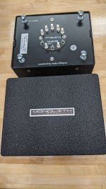
Monolith S11
OPT Primary 5KΩ
4 an 8 Ω Winding ratio 35.36 / 25.00 (Mine have 16Ω tap as well).
Thanks for your interest!
Goal is 405B+
Primary resistance of Edcor PWR077 2.1Ω (this PT gives me the proper B+) Heyboer 2.5Ω (gives me lower B+)
106mA comes from adding up the tube current from data sheets.
Bleeder/voltage divider 330K/47K with 3.3uf 630V cap.
The 5V floating winding is part of the PT secondary and is delayed as is the PT in its entirety.
There is a free floating 5V transformer to preheat the filaments of the 866a tubes that comes on ~120 seconds before the main PT.
I'm afraid these don't mean anything to me:
EF86, Ik or voltage over Rk ?
6S4A, Ik or voltage taken over Ra?
6S4A Uk/g1 ?
3C24, Ik ?
3C24, Uk/g1 ?
3C24, Uk/Ua ?
3C24 is preheated while 866s are warming up.
Transformer Info attached.
Monolith S11
OPT Primary 5KΩ
4 an 8 Ω Winding ratio 35.36 / 25.00 (Mine have 16Ω tap as well).
Thanks for your interest!
Attachments

My PSUD2 calculates the PT secondary effective resistance at 74 ohm, assuming a 120V primary. That indicates your B+ is circa 360V for 100mA load.
The other important design data is how you arrive at 105mA loading - ie. what is your idle current for each stage. Also elaborate on the the chosen idle current of the output stage, given a likely 25W plate max, and the indicated 55V drop on the OPT primary winding.
Are you indicating in the schematic that the 866 filament supply is 2.5-0-2.5V, rather than 1.25-0-1.25V (which would be the preference for lowest ripple).
I don't know how to answer most of your questions I'm afraid.
The 866a tubes are heated by a 2.5-0-2.5 transformer as you stated.
I just used the current draw from the data sheets, I'm not smart enough to do otherwise.
Thanks for the help!
The 866a tubes are heated by a 2.5-0-2.5 transformer as you stated.
I just used the current draw from the data sheets, I'm not smart enough to do otherwise.
Thanks for the help!
- Home
- Amplifiers
- Power Supplies
- What's Going On Here?