
 Hi,
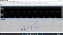
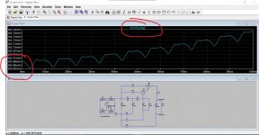
Hi,I'm wondering what is going on with the second trace here. The top trace is a typical ripple trace taken at the reservoir capacitor. I'm getting 41 mV of AC ripple content at that point. The second trace is my final output after the capacitor multiplier circuit shown. The cap multiplier is simply being fed from a bridge rectifier with a 10000 uf capacitor (3 parts transformer, bridge, cap) voltage here is 7.07 volts and as mentioned has 41 mv of ripple (top trace).
The output of the cap multiplier is loaded with a 25 ohm resistor drawing about 210 ma. It is removing much ripple I measure 1.5 mv of ripple here (second trace), so it is nearly pure DC.
What I am wondering is why my scope is showing the little scooped divots in the second trace? My scope is in "chop mode" to show both traces.
Note I'm only using the + side of the attached cap multiplier schematic. I'm very happy to get 1.5 mv even when tested at 3 amps of draw current.
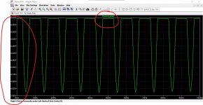
But was wondering if the second trace is normal looking for power with only 1.5 mv of ripple? It is mostly a flat line except for the divots.
Also ch 2 of my scope had to be set at under 5mv per step to the divots to show up even, if I set that channel to 50 mv per step then the second trace truly is just a straight line (DC?). Is it just that I'm setting the scope too sensitive?
ALSO: I'm not using a CT transformer like the schematic, Just a regular xformer into a bridge rectifier. Sorry I didnt re-draw the schematic.
I'm a newby/hobbyist not an electronics engineer.
Thanks
Last edited:
I made a small update to my post. I'm not using a center tapped transformer, just a bridge rectifier. Sorry I didnt take the time to redraw the schematic The only difference is that I'm not using a center tapped xformer. I only see the divots if my scope is set under 50mv setting and barely see them at 20 or 10 mv but at 5 mv scope setting they show as shown.
Your "divot" goes down exactly when the capacitor charges up, right?
Then it is IR drop in the return side of the rectifier.
It may be *critical* to show exactly what you built and where you are probing. (Not likely the same as Rod.)
Then it is IR drop in the return side of the rectifier.
It may be *critical* to show exactly what you built and where you are probing. (Not likely the same as Rod.)
I suspect that the 12K resistor is discharging its cap, causing an issue.
Try removing it, and allowing the caps to retain their charge, or replace the 12K with an appropriate zener diode.
Try removing it, and allowing the caps to retain their charge, or replace the 12K with an appropriate zener diode.
It is more lickely what PRR said.
Read carefully what Rod Elliot explains about layout and ground routing which he mentions critical for cap multipliers to, do get very good ripple reduction.
Here is an example that "the map is not the territory".🙂
Read carefully what Rod Elliot explains about layout and ground routing which he mentions critical for cap multipliers to, do get very good ripple reduction.
Here is an example that "the map is not the territory".🙂
I guess the main 10 000 uF cap sits somewere a bit 'aside' of the whole circuit (I totally agree with PRR).
I suspect that the 12K resistor is discharging its cap, causing an issue.
Try removing it, and allowing the caps to retain their charge, or replace the 12K with an appropriate zener diode.
I’m thinking the opposite. The 12K ohm resistance is too large, leaving not enough dropout voltage for the emitter followers.
It is more lickely what PRR said.
Read carefully what Rod Elliot explains about layout and ground routing which he mentions critical for cap multipliers to, do get very good ripple reduction.
Here is an example that "the map is not the territory".🙂
Yes I suspect that is it. This is on a breadboard proto board and you know with those the jumper wires are only 24 gauge and long. So what I'm going to do is build it for real on a tag board with short leads and the star ground. The 12k resistor has no effect if removed or changed to a lower value. It's got to be these thin and excessively longer wires that are probably causing a drop as the reservoir is charging.
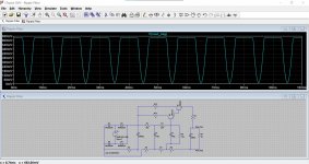
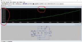
Here is a quick sim of your circuit. Ripple should be very low.
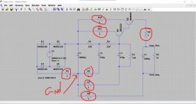
Wow thanks, (I wish I had the time and patience to learn LT Spice). I should have mentioned at the outset that this is Rod Elliots circuit and can be found here (figure 3 is what I built just the + leg no CT):
Capacitance Multiplier Power Supply Filter
If you install LT the file I attached will just click and run 🙂 and you can easily alter values.
Click my signature line to see how to get started.
Click my signature line to see how to get started.
> the file I attached
Yeahbut... a "simple" spice has no wiring resistance. But a real cap-input rectifier and filter is very sensitive to parasitic impedances and circuit layout.
Yeahbut... a "simple" spice has no wiring resistance. But a real cap-input rectifier and filter is very sensitive to parasitic impedances and circuit layout.
That is true PRR, however it is relatively easy to make wiring resistances 'disappear' in a real build. Circuit layout is important I agree.
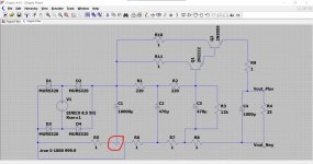
Here it is with 1 ohm series resistance all over the place. As long as you stick to the rule of having a single ground reference point the additional resistance causes no issue apart from a linear volt drop that is load dependent.
The last three images show 'bad practice'.
Also as I mentioned earlier, inadvertent loops formed from test equipment ground leads can appear to show a problem when one doesn't actually exist.
Attachments
-
 Screenshot 2020-10-09 073620.jpg347.4 KB · Views: 70
 -
 Screenshot 2020-10-09 073447.jpg265.2 KB · Views: 74
 -
 Screenshot 2020-10-09 073418.jpg314.6 KB · Views: 124
 -
 Screenshot 2020-10-09 073009.jpg315.8 KB · Views: 128
 -
 Screenshot 2020-10-09 072941.jpg306.9 KB · Views: 125
 -
 Screenshot 2020-10-09 072135.jpg403 KB · Views: 125

> the file I attached
Yeahbut... a "simple" spice has no wiring resistance. But a real cap-input rectifier and filter is very sensitive to parasitic impedances and circuit layout.
Thanks PRR. It ran very stable all night the pass transistor stays at 81 degrees in a 73 degree house with no heatsink. The load resistor is 25 ohms the voltage drop across it is the red meter 5.29 V. I'm gonna need 1.5 amps I dont think it'll be a problem. So I dont think its a wiring error, its got to be the layout. The board on the left is the Schottke diodes and reservoir, the board on the right is the filter. Note all the thin jumper wires all grounded to the breadboard rail. It could very well be the probe too but for now its time to solder. But the fluke still says 1.2mv of AC, so I'm happy. And that number should go down once its built properly because a portion of that 1.2 mV is probably including the divot too right?
Last edited:
- Home
- Amplifiers
- Power Supplies
- Whats causing these trace divots after cap multiplier?