quick update, replaced all 4 XLR inputs, sex changed and switched hot and cold, so now conforming with modern standards. Connected up with a stunt speaker, and played directly from pre (SE) and just the bass from dbx crossover (balanced) 3 channels good, have to put my ear up very close to speaker to hear the faintest hiss. Channel 1 is bad, playing, but much louder buzz/hissing sound. Hoping its a bad cap, I haven't changed over the 44 ROE caps on the 4 boards, so that will be next job, plus making up 3 more speaker cables with XLR connectors. Not able to do any critical listening, but a fairly positive start.
I've kept the pin 1,2, chassis ground connected, as that was how it was originally, but will try breaking link to pin 3 to see if that reduces the tiny amount of hum, but fairly sure this will not make any difference.
I've kept the pin 1,2, chassis ground connected, as that was how it was originally, but will try breaking link to pin 3 to see if that reduces the tiny amount of hum, but fairly sure this will not make any difference.
Last edited:
Hint: change caps 2 at a time then listen. I make a lot of soldering mistakes, you may not be a lot better. If one makes a mistake and sound checks afterwards, if sound got worse, you know just where the problem is.
Unusual hiss is sometimes bad solder joints or a bad weld inside a resistor, so good luck on cap patrol.
Unusual hiss is sometimes bad solder joints or a bad weld inside a resistor, so good luck on cap patrol.
Thanks, that's a great tip. Most of the ROE are accessible with the amp boards in place, (amp unit/wings removed from main chassis), sadly 2 or 3 are not, so will have to remove the PCB from the wing. Not horrible, but more work and more care will be needed, I will leave those till last. Have a nice set of Nichicons ready to go in.
I use 70% alcohol on a paper towel, pushing around small components with a screwdriver and or a pick. For really fine stuff I use a cotton ball.
I don't see much knowledge gained by inspecting cases of old electrolytic caps for damage. Yes, pushed out ends and a puddle of cap slime is a good indicator. Usually they are garbage long before that happens. The little ones never pop, they just quit passing sound, or not enough, due to high ESR. I bought a Peak ESR meter, but it wasn't a lot of help. Looking at production date versus the calender on my wall is the best prediction of e-cap condition. Plus the reputation of the manufacturer. Apex dtv converters, bad from the store. PCAT supplies from the local computer shop, 2 years. PCAT supplies from Newark, 10 years. Peavey amps, 15 or 20 years. Fender guitar amps from the 70's with the green CDE epoxy sealed caps, forever.
To make board function testing easier, maybe a test jig with alligator clip leads from the case rail capacitors to a board sitting out on your bench. Plus some sort of speaker hookup. I get trashy 8 ohm speakers for testing from charity resale shops for a coupla dollars. >1000 uf negative to negative series the speaker protects even the $2 speakers from unwanted DC, at the cost of a little distortion (not much).
Last edited:
Good advice from Indianajo. It may be added that a toothbrush dipped into iso-propanol helps cleaning without damage.
That's a 35 year old amp. I would say that all of the electrolytics should probably be replaced. The schematic indicates that each amp is really operated as single ended, so I would have replaced the (gender incorrect) XLRs with RCAs. As far as the op amp is concerned, a 5532 might be better. Even if it is, it might not be audible for your intended purpose. Still, it's in a socket, so easy enough to try out (and really minimal risk that the swap will make anything not work). Many (maybe most) of the signal path caps might be suspect due to age, but I would change those last unless there's clearly something wrong.
As to why 1 channel isn't working right - this sounds like a failed component to me. If you can't see any visual damage (physical or heat damage on the PCB), it'll be a slow game of detective replacing parts until it works. I would start with by cleaning the PCB and looking carefully if there are any suspect solder joints. Resolder anything that looks even minimally suspicious. Likewise all of the wires running to/from the PCB. Check the solder joints and jiggle the wires around to see if something changes. Next I'd replace the op amp as it is cheap and will take seconds to replace (not that I really suspect it to be bad). Next I'd do the caps as resistors rarely fail without some physical signs.
As for the front panel: Unless you like working with metal, how about a thin piece of hard wood sanded smooth and painted as you like. Simply glue that over the offensive front panel. For an LED indicator: I assume that the power rails are around ±50V or so. Simply use any LED that suits your fancy and connect it to one power rail through a 5k to 10K resistor. (the other side to ground, obviously) If you want it brighter, lower the resistor value and vice versa.
I use 70% alcohol on a paper towel, pushing around small components with a screwdriver and or a pick. For really fine stuff I use a cotton ball. ..... Snip).
That being said, BIG lytics often last very very long. I am working on repurposing a Krell KMA200 1988 vintage, and all the caps in that are still within spec.
Knost - probably so, but when they fail they do so dramatically! Besides, if you're going to do a bunch of work rehabilitating an amp you would want it to work right for another 20 years. Do you think those electrolytics will last 55 years??? That's why IMHO once you are elbow deep into a project like this you may as well change the big filter caps.
Side note. I had a buddy of mine who used to rehab old electronics. Anything that didn't have a paper cap would get partially disassembled, blown free of big dust/debris with a compressor, and then popped in the dishwasher!!! He did take some very minor precautions, like using cheapo dishwasher detergent that didn't have rinse agent and doing a double rinse, and he also skipped the heated drying cycle but that was it. He claimed that the dishwasher never hurt anything he put in there that wasn't already broken. I do have to admit everything came out looking very clean indeed...
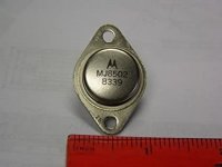
Am I mistaken or are the outputs fake? I've never seen Motorola/on semi with lettering like those. Generally all Japanese TO-3's have lettering that goes in that direction. I do think the outputs are fake. Not enough outputs to drive a low impedance load (my opinion) or low frequency load. I wouldn't have bought it. You could have purchased a Altec 9444 or EV2600 for the same price and it would have been a superior amplifier. There is a point where your time and effort are not justified in a project and this is one in my opinion.
A picture of a 1983 vintage Motorola transistor.
A picture of a 1983 vintage Motorola transistor.
Attachments
Last edited:
I get old PC supplies very cheap, and wash the boards in cheap dishwash liquid, fans are lubricated with oil and grease, and the capacitors changed out if they look bad.
They do get quite clean, I use an old tooth brush.
After drying them, generally next day, I check outputs, then varnish the PCB on the solder side, to prevent flash over from dust getting damp.
Dust accumulayes between PCB and case, and our monsoon means months of humid weather, and SMPS repair/replacement season.
Reason for getting old supplies is that the newer ones have small heat sinks, and no NTC or MOV to protect the circuits as a cost cutting measure. The main caps are bad,,,in my old ones I have Nichicon and Keltron.
And the new all in one PCs seem to have a single 12 volts brick, so they wont work on old PCs like mine.
I would suggest a total electrolytic replacement with good caps, but if the originals are of good quality, and the set has been in use, perhaps a physical and meter inspection in advance could save you some work.
Good caps means reputed high quality manufacturers....Vishay, Wilna, all Japanese, Keltron in India, Sprague, Taicon from Taiwan.
Generally Chinese are cheap junk.
Last edited:
- Home
- Amplifiers
- Solid State
- what would you do with this beast? calling power amp experts