Hi all,
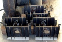
I bought these PT’s 20 years ago on a discount shelf at the local electronics store. I’d love to build amps with them but they have low current and high voltage. I read a little about wiring the transformer to double the current capacity, but not sure how to do this. Any thoughts on how turn these into a nice projects?
I bought these PT’s 20 years ago on a discount shelf at the local electronics store. I’d love to build amps with them but they have low current and high voltage. I read a little about wiring the transformer to double the current capacity, but not sure how to do this. Any thoughts on how turn these into a nice projects?
Attachments
The 7104 would be fine for a preamp build. It sure isn't rated for much current, but most preamps don't need a whole ton of DC current anyway.
The 71B06 would possibly be a decent match for a small single ended amp. Maybe an RH807 build would be a decent choice.
The 71B06 would possibly be a decent match for a small single ended amp. Maybe an RH807 build would be a decent choice.
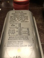
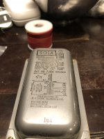
These are not standard power transformers:
What is a Constant Voltage Transformer - an introduction to the perfect sine wave
What is a Constant Voltage Transformer - an introduction to the perfect sine wave
They'll hum like no tomorrow, and they need to be run close to specification and regardless of the load they'll consume about the power they are rated for. Magnetic field is rather strong around them so using a tetrode in the neighbourhood is a bad idea. How do I know that? Yeah, you got it, I won't touch them again.
These Sola CVT's are indeed a different breed of transformer. The previous link does describe them in detail. We used some very large ones at work (Motorola) to power some ATE equipment that would spontaneously reboot from line spikes. Nothe that the output voltage waveform is a near perfect sine wave since the secondary operates in resonance. The input CURRENT waveform is not usually sinusoidal and depends on the applied load. These can put noise back into the power lines.
Remember the word RESONANCE used to describe the operation. A specific capacitor MUST be placed across the secondary, or seperate resonating winding for these to be resonant, and operate correctly. With the wrong cap, or no cap, the secondary voltage will be wrong, distorted, and vary greatly with load.
Resonance REQUIRES a specific operating frequency, and these transformers MUST be used at the specified frequency. I can't read the frequency of operation on one of the pictures, but the other clearly states 50 Hz.
In theory the frequency of operation can be shifted by using a different resonating capacitor. I had a couple of large (75 V at a few amps) rack mount SOLA power supplies. They were 50 Hz units and no combination of caps that I could find would make them work at 60 Hz. The were sold for the metal scrap value.
In theory the frequency of operation can be shifted by using a different resonating capacitor.
Good luck finding the right alternative value! Recalling that (LC circuit - Wikipedia midpage)
f₀ = 1/(2π√(LC))
, solving for f₀ = 50 Hz, C = 1 µF, we find L = 10.3 Hy, and therefore, reevaluating at f₀ = 60 Hz, gives C = 0.694 µFWhich is a hard-to-find value, no matter how dearly one might want to find it.
⋅-⋅-⋅ Just saying, ⋅-⋅-⋅
⋅-=≡ GoatGuy ✓ ≡=-⋅
I guess I'll put them up on ebay and hope someone can use them. Thanks everyone for the explanation of what these really are!
C = 0.694 µF Which is a hard-to-find value, no matter how dearly one might want to find it.
Microwave oven capacitors come in flavors from 0.8 to 1.2 uF at 1500+ volts.
The PIO can caps from old military surplus tube gear are also suitable, as are some modern safety caps rated to operate across the AC line.
It should be possible to make something work with series, parallel or both combinations. I could not get either of the two power supplies that I had hold a steady output voltage under load no matter what combination of PIO caps I tried. Granted this was about 50 years ago and the power supplies were also quite old then (made in 1965).
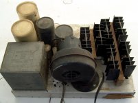
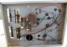
I reused the rectifiers and output caps to make a big solid state amp, that I kept for nearly 40 years. The caps and diodes can be seen in the photos. I was a 17 year old kid when I made this amp. My construction skills are still not so great, but I have better tools. This was made with a hacksaw, a nibbler, and a old drill.
Attachments
- Home
- Amplifiers
- Tubes / Valves
- What tubes can I use these power transformers with?