Following traces it looks like the SG (two grounds coming in from source, right?) connect to the SG pin as shown in your v2 guide. The PG (power ground, right?) looks like it only connects to the lower right hand pin. Should I then add a jumper from the PG to the SG pin?
Following traces it looks like the SG (two grounds coming in from source, right?) connect to the SG pin as shown in your v2 guide. The PG (power ground, right?) looks like it only connects to the lower right hand pin. Should I then add a jumper from the PG to the SG pin?
You can try that. It isnt the best place. I would go PG in to SG in.
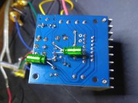
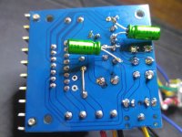
Maybe a better picture of the bottom will help, I can't tell what's going on with the one you posted because I can't really see the lines between the copper traces.
okay, so looking at my own pictures I realize I was confused about the traces in my earlier post by the speaker wire (which I disconnected for these pics). It looks like the pg and sg are connected on the board, I think🙂 Hope these pics are more clarifying
Attachments
did another ver.1 without removing the mini-jack and pot. (bought plenty spare parts, planned on burning some stuff up but my soldering is getting a lot better. all credit to the new Weller WTCPT!) This guy works great!
Probably need fresh eyes, I do not see anything obviously wrong.
But some of these 2nd's chips are not good.
Maybe the vias pulled out with the 1/8 jack? You could bypass the jack vias straight to the wires going to the pot, with incoming wires, see if it works.
But some of these 2nd's chips are not good.
Maybe the vias pulled out with the 1/8 jack? You could bypass the jack vias straight to the wires going to the pot, with incoming wires, see if it works.
Last edited:
sffrhd..
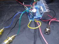
Try shorting the audio input connections. I suspect the length of unshielded wiring between the board and the RCA connectors could be the issue. (High Impedance) If you have a ground loop isolator laying around, try it..
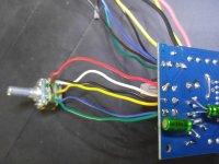
I wouldn't discount the wiring between the volume control and the board. It's unshielded also and high impedance. Short the Green/Black and Blue/Yellow at the volume control and see if the hum goes away..
Try the RCA input test first.. 😉
Try shorting the audio input connections. I suspect the length of unshielded wiring between the board and the RCA connectors could be the issue. (High Impedance) If you have a ground loop isolator laying around, try it..
I wouldn't discount the wiring between the volume control and the board. It's unshielded also and high impedance. Short the Green/Black and Blue/Yellow at the volume control and see if the hum goes away..
Try the RCA input test first.. 😉
Thanks OGKG and DestroyerOS,
Went through all your suggestions, started getting some music but still just as much noise. Was kinda making a mess so I went to my second build and made the same connections one step at a time. Still had noise at first but I think I had ground problems and a bad cable, managed to get it working! Listening to some sweet Beth Orton through it right now! Maybe a bad chip on the first one or maybe I just buggered up the board, frustrating but made me think about the circuits instead of just dumbly following a build guide. Thanks again and now on to ver. 2 for more practice so I don't butcher those nice boards DestroyerOS sent me.
Doug
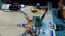
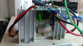
I am amazed by the music from this chip !!! Paired with Markaudio 12p, it is highly detail , dynamic and realism is unbelievable.
I build this from one of the us1 kit from China.
I notice that the local power supply bypass is critical .
The voltage step up and juma cap multipier are based on recommendations from xrk.
I build this from one of the us1 kit from China.
I notice that the local power supply bypass is critical .
The voltage step up and juma cap multipier are based on recommendations from xrk.
Attachments
I'm wanting to connect an xlr +4db signal to a TDA7297 input. Do I need to take any special precautions?
What voltage step up? Can you elaborate, please?<snip>The voltage step up and juma cap multipier are based on recommendations from xrk.
Ya... you need to turn it into a single ended signal... you cannot convert the 7297 for balanced inputs.
What voltage step up? Can you elaborate, please?
I use a 12 V 4A smps power supply. I step it up to 18V and feed the JUMA cap multiplier . after the multiplier it is about 15V. My speaker is 6ohm.
I am amazed by the music from this chip !!! Paired with Markaudio 12p, it is highly detail , dynamic and realism is unbelievable.
I build this from one of the us1 kit from China.
I notice that the local power supply bypass is critical .
The voltage step up and juma cap multipier are based on recommendations from xrk.
Nice work Kp93300! You can see the power of the DC step up and cap Mx. Now, take about 16 x 1000uF 25v caps (cheap Aliexpress ones are fine) as they measure about 0.060ohm ESR. Bundle them together in a 4x4 array and use thick solid 12ga copper (from house mains) to solder up the caps to form a very low impedance array in parallel. 0.060ohms/16 is 3.8mOhm ESR. Use thebcap Mx to feed the cap array and use thick 16 ga stranded copper wire to connnect the cap array to the amp.
Now listen to the improved bass dynamics and it only costed an extra $2 in caps from China.
Bag of 50 caps 1000uF 25v for $3. You need 32 of the 50. You can use all 50'if you want for a 5x5 array. Note that this cap array would not work with the DC step up without a cap mx. It would shut down because of the low ESR (it thinks it is a short as ESR is 3mOhm). But the cap Mx ramps up slowly allowing the DC step up not to choke up and reset.
CNIKESIN 50PCS 25V1000UF new genuine high quality power supply line super electrolytic capacitor 1000UF 25V 10X17mm-in Capacitors from Electronic Components & Supplies on Aliexpress.com | Alibaba Group
Last edited:
xrk.
Bought some caps from the site last night.
Will incorporate your suggestions for more fun !!
thanks
kp93300
Bought some caps from the site last night.
Will incorporate your suggestions for more fun !!
thanks
kp93300
xrk and kp93300:
Is [URL="http://www.diyaudio.com/forums/group-buys/309860-folsom-diy7297-amp-antipole-psu-post5145678.html]this[/URL] [Post # 58] the schematic of the CAP-X?
Is [URL="http://www.diyaudio.com/forums/group-buys/309860-folsom-diy7297-amp-antipole-psu-post5145678.html]this[/URL] [Post # 58] the schematic of the CAP-X?
Last edited:
- Home
- Amplifiers
- Chip Amps
- What the heck? It's less than lunch!