Hello, this have probably been asked several times before but my searches yeilded nothing that realy helped me.
i have some problems. i want to have a swich so i can change source but i dont realy know what switch to use(so super expensive stuff thanx) i want to be able to select three different sources how manny poles resp pos do i need the rotary switch to have?
and after looking att one just now i realised i have no idea what so ever how to wire it
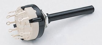
I assume that you are going to use the swith to select stereo line level sources before a power amplifer ??
If so, look at www.elfa.se and write 35-490-60 in the "søk felt". This is probaly the cheapest switch you can get.
If so, look at www.elfa.se and write 35-490-60 in the "søk felt". This is probaly the cheapest switch you can get.
Attachments
yes that is what im looking for, but i still dont know how many poles and poses it should have, 3p3t? 3p4t? its three (all in stereo but maby you figured that out ) line in's that i want to be able to switch between
) line in's that i want to be able to switch between

RCA selector problem
I have a similar problem, I have a 4 selector switch (I think) with 4 outer and one inner row on each half of the switch as can be seen.
on selector set at position 1, A,B and C,D are connected as pictured (measuring from multimeter).
I can not figure out 1) where the wires from RCA input jacks (for selector at position 1) should be connected to.
2) where the common RCA output jacks should be connected?, eventually feeding the amplifier.
I would appreciate any help from the experts for this newbie.
gychang
I have a similar problem, I have a 4 selector switch (I think) with 4 outer and one inner row on each half of the switch as can be seen.
on selector set at position 1, A,B and C,D are connected as pictured (measuring from multimeter).
I can not figure out 1) where the wires from RCA input jacks (for selector at position 1) should be connected to.
2) where the common RCA output jacks should be connected?, eventually feeding the amplifier.
I would appreciate any help from the experts for this newbie.
An externally hosted image should be here but it was not working when we last tested it.
gychang
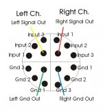
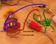
Connect your inputs to the outer rows (eg. right channel to A and the three pins going left on the outer row and left channel to D and three right) and connect B to right channel input and C to left input of your preamp 😉
ACD said:Connect your inputs to the outer rows (eg. right channel to A and the three pins going left on the outer row and left channel to D and three right) and connect B to right channel input and C to left input of your preamp 😉
right channel (red) from input 1 (2 leads) both are combined and soldered to A?
will try this today. thanks,
gychang
with a 2 pole switch you will have to connect input grounds together on some kind of ground bus and run a wire to the amp's -input.
In other words connect just the hot lead of your signal cable to the switch , the ground will have to bypass it....
with a 3 pole switch you can also connect a commoned ground fro the 2 channels..
and with a 4 pole switch you can connect input earths, and keep them seperate, but you are likely to have only 3 selection positions.
I.e. your switch is not ideal
Nordic said:with a 2 pole switch you will have to connect input grounds together on some kind of ground bus and run a wire to the amp's -input.
In other words connect just the hot lead of your signal cable to the switch , the ground will have to bypass it....
with a 3 pole switch you can also connect a commoned ground fro the 2 channels..
and with a 4 pole switch you can connect input earths, and keep them seperate, but you are likely to have only 3 selection positions.
I.e. your switch is not ideal
I am a newbie and confused. How do I find out what kind of "pole switch" I have. Anyway from looking at the picture?
An externally hosted image should be here but it was not working when we last tested it.
Assuming it is a 2 pole switch, I run hot from input 1 on A and D? and I am not sure how the statement "ground will have to bypass it" should be setup.
thanks for trying to help.
gychang
gychang said:
I am a newbie and confused. How do I find out what kind of "pole switch" I have. Anyway from looking at the picture?
Assuming it is a 2 pole switch, I run hot from input 1 on A and D? and I am not sure how the statement "ground will have to bypass it" should be setup.
thanks for trying to help.
gychang
Go to Radio Shack or Harbor Freight and buy a cheap multi-meter. Measure resistance or continuity from pin to pin in each position.
Make a chart:
Position 1, pin A to ?
pin B to ?
Position 2, pin A to ?
pin B to ?
Kevin Graf said:
Go to Radio Shack or Harbor Freight and buy a cheap multi-meter. Measure resistance or continuity from pin to pin in each position.
Make a chart:
Position 1, pin A to ?
pin B to ?
Position 2, pin A to ?
pin B to ?
I already have a multimeter.
I have continuity at position 1: pin A to B and C to D.
position 2 (next to A pin on the outer to B, next to E (on the outer row) to C. etc to position 4
what I can't figure out is how I should connect the output (to amplfier leads).
gychang
That is a 2 pole switch.... ie it can switch 2 poles (the 2 centre pins) and it is a 4 way i.e. it can switch those 2 poles between the 4 tabs on the outside... connect a multimeter on diode test to a middle tab then find wich outer tab connects to it... do the same for the other inner tab and find its outer tab... now you know what the switch does.
If you want to order one from an online catalog, go for a 3- or 4-way make-before-break switch 3P4T (3 pole) or 4P3T (4 pole).
If you want to order one from an online catalog, go for a 3- or 4-way make-before-break switch 3P4T (3 pole) or 4P3T (4 pole).
Attachments
Nordic said:That is a 2 pole switch.... ie it can switch 2 poles (the 2 centre pins) and it is a 4 way i.e. it can switch those 2 poles between the 4 tabs on the outside... connect a multimeter on diode test to a middle tab then find wich outer tab connects to it... do the same for the other inner tab and find its outer tab... now you know what the switch does.
If you want to order one from an online catalog, go for a 3- or 4-way make-before-break switch 3P4T (3 pole) or 4P3T (4 pole).
wow!, thanks for the drawing, I get the overall picture. How do I make a "ground bus", does it need to be connected to a chassis or PC board or do I need a part?
next time I will get a proper switch like this?
http://www.allelectronics.com/cgi-bin/item/RS-134/700425/ROTARY_SWITCH,_4_POLE_3_POSTION_.html
gychang
No don't make this groundbus the same as the power ground star...if the circuit requires it, you can run a thin wire between this audio groundbus and the power one....
You will get some chirps from the people here, and the main reason you are haveing so few replies, is because your solution is so far from the "ideal"...
I say, what the heck, try everything once!
For the ground bus a little piece of copper plate or maybe some thick copper wire can do.
The new switch you are looking at, will be much better.
Nordic said:No don't make this groundbus the same as the power ground star...if the circuit requires it, you can run a thin wire between this audio groundbus and the power one....
You will get some chirps from the people here, and the main reason you are haveing so few replies, is because your solution is so far from the "ideal"...
I say, what the heck, try everything once!
For the ground bus a little piece of copper plate or maybe some thick copper wire can do.
The new switch you are looking at, will be much better.
thanks for all your input. will get on it this weekend.
gychang
4P is 4 pole, 3T is triple throw. like a SPDT switch would have a single pole and select between 2 outputs. I bought some 2P6T ones at Radio Shack (an American outfit), but have yet to use them.
- Status
- Not open for further replies.
- Home
- Design & Build
- Parts
- what source selector rotary switch and how to wire it