I'm not sure if this is the right section for this, so can a mod please move if it's wrong...
I want to build this... I'm planning on 112.5Hz crossover frequency.
http://sound.westhost.com/project09.htm
This is going to be in a car, so hifi quality isn't really 100% needed.
I have a bunch of 4558D chips on an old car amp I can use, but these look like they are poor quality from what I've read here.
So can someone recommend me an op amp? I know next to nothing about them...
Hi,
the 5532 can be used for the input buffers.
tl072 or other FET input opamp works for the filter stages.
The output buffers could be another 5532.
If you use tl072, ensure the parasitic capacitance on the outputs of the opamps is minimised. They don't tolerate capacitive loading.
the 5532 can be used for the input buffers.
tl072 or other FET input opamp works for the filter stages.
The output buffers could be another 5532.
If you use tl072, ensure the parasitic capacitance on the outputs of the opamps is minimised. They don't tolerate capacitive loading.
In reference to previous post, I'm aware of the need to protect chips such as the TL072 from capacititive loading, but just how close to the output pin does the low value R need to be?
Often find myself laying out a circuit and getting nervous about moving the resistor millimetres away.
Also, if a blocking cap is to be used, is there a problem to place it after the load resistor rather than before, as this often allows closer placement of the resistor to the output?
Often find myself laying out a circuit and getting nervous about moving the resistor millimetres away.
Also, if a blocking cap is to be used, is there a problem to place it after the load resistor rather than before, as this often allows closer placement of the resistor to the output?
Mike,
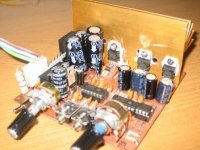
I did that project using TL074 .
I'm using it in a work in progress 2.1 PC sound speaker.
I use ground plane layer and 78xx based PSU.
I drive TDA2003 and TDA2030 directly. I'm planning to change these by lm1875.
Sound is good. No noise No hum
Best,
Tincho
I did that project using TL074 .
I'm using it in a work in progress 2.1 PC sound speaker.
I use ground plane layer and 78xx based PSU.
I drive TDA2003 and TDA2030 directly. I'm planning to change these by lm1875.
Sound is good. No noise No hum
Best,
Tincho
Attachments
The 4558 is a very dated opamp. Used extensively many moons ago, but long superseded by better devices which will not cost you an arm and a leg.
The posters have already made several suitable suggestions above. I've used every single one of those suggested devices and can tell you it will be plenty, for the application you are looking for.
However, I would add to add to the list the BiCMOS cousins of the deservedly famous TL07x BiFET family....For instance the TLC072. They offer several improvements over the standard family, yet they are quite affordable. check yourself this link.
http://focus.ti.com/lit/ds/symlink/tlc072.pdf
Thanks for the recommendations guys - I only know a little opamp theory, I must admit I haven't a clue what the difference is between a 5532 and a TL074, but I looked up the datasheets which helped a little...
Anyway, am I right in assuming that all these opamps run from +-15v rails? and they use very little power? So would I be able to run 10 op amps with unsinked 7815's? My amps rails are +-24v so the 7815 will only be dropping 9v or so. 🙂
Just 1 quick question, if I wanted to adjust the volume of the LP out and HP out independently, could I just wire in a 10k log pot in the same way as a normal volume pot at the LP out an HP out? My amps gains are in the boot(trunk), so they won't be very easy to adjust while driving. 😉
Anyway, am I right in assuming that all these opamps run from +-15v rails? and they use very little power? So would I be able to run 10 op amps with unsinked 7815's? My amps rails are +-24v so the 7815 will only be dropping 9v or so. 🙂
Awesome - I think I'll just copy what you did if that's ok, as I'm a bit overwhelmed with all these different opamps right now. 😱 Obviously with different value caps and resistors as I want a different crossover point.juma said:
Just 1 quick question, if I wanted to adjust the volume of the LP out and HP out independently, could I just wire in a 10k log pot in the same way as a normal volume pot at the LP out an HP out? My amps gains are in the boot(trunk), so they won't be very easy to adjust while driving. 😉
As far as I knew the op-amps should be FET input to ensure high input impedence? This stops the thier input impedence from affecting the predicted response. The 5532 isn't, but can be used for the buffers. I have used OPA2134 chips and been quite satsfied; FET input and unity gain stable. A very low distortion chip too 🙂
MikeHunt79 said:
So would I be able to run 10 op amps with unsinked 7815's? My amps rails are +-24v so the 7815 will only be dropping 9v or so. 🙂
Awesome - I think I'll just copy what you did if that's ok, as I'm a bit overwhelmed with all these different opamps right now. 😱 Obviously with different value caps and resistors as I want a different crossover point.
Just 1 quick question, if I wanted to adjust the volume of the LP out and HP out independently, could I just wire in a 10k log pot in the same way as a normal volume pot at the LP out an HP out?
1. If it's not a big trouble for you, you'll get better results with mildly heatsinked LM317/LM337
2. Of course it's OK, that's what this forum is all about - to share ideas and help each other.
3.Yes, you can use 10k log pots to independently control HP and LP volume, but you'll need to use bigger coupling cap (4.7 uF) on LP output.
You;ll need to do something interesting for the power if you run it off 12 volts DC in a car.
Perhaps using 0V 5V and 10V for a pseudo +/- 5V.
you'll need to capacitor couple the input and output audio grounds if you do that.
Perhaps using 0V 5V and 10V for a pseudo +/- 5V.
you'll need to capacitor couple the input and output audio grounds if you do that.
juma said:
Juma, I notice on your schematic that you have seperate PS and signal grounds marked. Are these grounds just seprated on the board but fed from a single cable to the star or central grounding point, or are they seperated all the way back to star ground?
Is it normal practice for you to seprate your grounds or only for certain circuits?
This is something I've been reading on recently and it doesn't seem to be at all straightforward so I'd be interested in hearing about your approach. Thanks.
I've already got some 7815's handy, so I'll use them for now...juma said:
1. If it's not a big trouble for you, you'll get better results with mildly heatsinked LM317/LM337
2. Of course it's OK, that's what this forum is all about - to share ideas and help each other.
3.Yes, you can use 10k log pots to independently control HP and LP volume, but you'll need to use bigger coupling cap (4.7 uF) on LP output.
Also, I've discovered my headunit is has 4 channel pre-out, so this has changed things a little... I was thinking of using channels 1 & 2 for L&R above 112Hz, and use channels 3&4 summed together below 112Hz...
This should make things simpler, as I'll need less filters and maybe less input and output buffers (I think)...
I'm still getting to grips with eagle, I only got it today, and I'm hoping to put together a schematic, which should show more clearly what i plan to do with the extra channels....
This won't be a huge problem, as I already have an amp with +-24v rails.OzMikeH said:You;ll need to do something interesting for the power if you run it off 12 volts DC in a car.
Perhaps using 0V 5V and 10V for a pseudo +/- 5V.
you'll need to capacitor couple the input and output audio grounds if you do that.
I've adapted this circuit a little: http://sound.westhost.com/project05.htm
This should work shouldn't it?
Also, does anyone know where I can get the eagle library which has the 1n5818 in? I ended up using a renamed 1n5400 for now...
Attachments
Ok, I've ordered a load of TL072's. 🙂
I've got 8 pin sockets handy, so I can use them and use my 4558's while I'm waiting for the TL's to arrive.
Anyway, I'm stuck... I've found a voltage summer here:
http://users.cscs.wmin.ac.uk/~wooda/components/opamps/
Now, the part which concerns me is "R5 should be parallel combination of R1-4 (R1-3 including source impedances)."
I'm not really sure what the source impedance is, but would using input buffer solve this? Or could I just get rid of R5 and have an inverting summer?
I'll post the schematic so you can see what I'm trying to achieve...
Attachments
- Status
- Not open for further replies.
- Home
- Amplifiers
- Chip Amps
- What op amps are good for this crossover circuit?