There is nothing strange about that ... 🙄
Here
Thank you very much Alain! 😉
Do you have by chance a picture of 6F5P internals?
It is hard to see from outside... It indeed may be a ray tetrode, for example 6J5P is ray tetrode actually, but is drawn and called usually "pentode". Also, there are miniature tubes that have no grids at all, but they are called pentodes. The example is 1J17B that has electrodes made of parallel rods.
http://www.diyaudio.com/forums/tubes-valves/191183-anyone-have-experience-1j17b-tube.html
Beam tetrodes were American response to European patent on pentodes. Later so called Kinkless Tetrodes were designed...
Last edited:
This come from your 6F5P datasheet :It is very strange because I never saw 6F5P datasheet that describes it as a ray tetrode.
European analog ECL85 is triode-pentode as well: ECL 85, Tube ECL85; Röhre ECL 85 ID18599, Triode-Pentode
An externally hosted image should be here but it was not working when we last tested it.
Clearly, I should not call it a "triode/pentode tube" but a "triode/beam power tube", that's what the symbol suggest ... 🙂
But it reads, "триод-пентод" right on the top. Who made a mistake: who drew the picture, or who wrote description? 😉
I just look at some octal "beam power" tubes ( 6V6, 6W6, 50L6, etc ) and it is impossible to see the "beam-forming plates" inside, they are enclose into the plate electrode ... The only way to see them is breaking the tube with a hammer or plugging the heater directly to the 120VAC ... 😀Thank you very much Alain! 😉
Do you have by chance a picture of 6F5P internals?
It is hard to see from outside ...
I just look at some octal "beam power" tubes ( 6V6, 6W6, 50L6, etc ) and it is impossible to see the "beam-forming plates" inside, they are enclose into the plate electrode ... The only way to see them is breaking the tube with a hammer or plugging the heater directly to the 120VAC ... 😀
One member here couple of years ago posted X-Ray pictures of tubes.
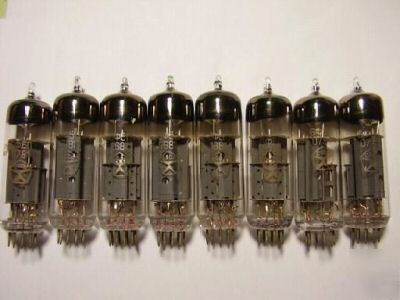
Here is a picture of pentode made by an ordinary camera:

Google translate said "триод-пентод" = "triode-pentode" and "pentode" = "пентод"But it reads, "триод-пентод" right on the top. Who made a mistake: who drew the picture, or who wrote description? 😉
But "tetrode" = "тетрод" and "beam power" = "мощности пучка" ...
Anyway, what is really important are the curves and specifications ... 🙄
Last edited:
Google translate said "триод-пентод" = "triode-pentode" and "pentode" = "пентод"
But "tetrode" = "тетрод" and "beam power" = "мощности пучка" ... 🙄
Right translation. "Beam power" translated into Russian means, "Power of Beam" that is something different. "Beam power tube" is translated as "лучевой тетрод", or "ray tetrode".
Here is an example, "Output Ray Tetrode":
Âûõîäíîé ëó÷åâîé òåòðîä 6Ï3Ñ. Òåõíè÷åñêèå õàðàêòåðèñòèêè
The curves of this tube look like any typical real "pentode" or "beam power tubes", "beam power tetrodes", "ray tetrode" or "kinkless tetrodes", whatever names are given to them ... Their electrical caracteristics are very similar but different from the reals "tetrode" with the kinks in their curves ! 🙂Right translation. "Beam power" translated into Russian means, "Power of Beam" that is something different. "Beam power tube" is translated as "лучевой тетрод", or "ray tetrode".
Here is an example, "Output Ray Tetrode":
Âûõîäíîé ëó÷åâîé òåòðîä 6Ï3Ñ. Òåõíè÷åñêèå õàðàêòåðèñòèêè
Yes, they are different: typical ray tetrode curves go sharper on high current/low voltage than pentode curves. On low current / low voltage they have "kinks" caused by Dynatrone effect. In 5-element tubes this effect is minimized by additional electrodes (3'rd grid or beam electrodes), in Kinkless Tetrodes it is minimized by proper spacing between 4 electrodes.
6P3S from my last link looks like typical 6L6 - like tube. I suspect it was designed as 807 for transmitters, and mass-produced by RCA as 6L6: as always, designed for military things are repackaged and positioned on the market for civil usage, in order to get some additional profit. 6L6 is actually quite bad tube for audio: you can see it from curves, it's transconductance continues still going up when control grid is positively driven. To be linear it has to be driven up to 150W of anode dissipation, but it would melt down on such power. The true picture about the tube can be seen in some British datasheet on their clone of 807 made for military usage in transmitters.
6P3S from my last link looks like typical 6L6 - like tube. I suspect it was designed as 807 for transmitters, and mass-produced by RCA as 6L6: as always, designed for military things are repackaged and positioned on the market for civil usage, in order to get some additional profit. 6L6 is actually quite bad tube for audio: you can see it from curves, it's transconductance continues still going up when control grid is positively driven. To be linear it has to be driven up to 150W of anode dissipation, but it would melt down on such power. The true picture about the tube can be seen in some British datasheet on their clone of 807 made for military usage in transmitters.
Yes, the 807 was first design for transmitters and the same engineer design the 6L6 some times later, both tubes have very close characteristics. The 6L6 spice models can to be used for the 807 and the 6L6 russian version 6P3S ...Yes, they are different: typical ray tetrode curves go sharper on high current/low voltage than pentode curves. On low current / low voltage they have "kinks" caused by Dynatrone effect. In 5-element tubes this effect is minimized by additional electrodes (3'rd grid or beam electrodes), in Kinkless Tetrodes it is minimized by proper spacing between 4 electrodes.
6P3S from my last link looks like typical 6L6 - like tube. I suspect it was designed as 807 for transmitters, and mass-produced by RCA as 6L6: as always, designed for military things are repackaged and positioned on the market for civil usage, in order to get some additional profit. 6L6 is actually quite bad tube for audio: you can see it from curves, it's transconductance continues still going up when control grid is positively driven. To be linear it has to be driven up to 150W of anode dissipation, but it would melt down on such power. The true picture about the tube can be seen in some British datasheet on their clone of 807 made for military usage in transmitters.
It is true that a lot of guitar amplifiers use 6L6 but not much HI-FI amplifiers ... 😀
...then the same engineer in 1938 published famous article how 6L6 can be used for audio. 😉
After that article on our forum local feedback in output stage is called by his name.
After that article on our forum local feedback in output stage is called by his name.
Beam Power Tubes by O.H. Schade 1938 ... A very interresting article !...then the same engineer in 1938 published famous article how 6L6 can be used for audio. 😉
After that article on our forum local feedback in output stage is called by his name.
Like you can see in my last schematics on this thread, Schade feedback work very well with triodes too, also JFET and MOSFET ... 🙂
You don't trust what write this students in our diagram,
look analogue and decide. Many diagram in principle don't work.
aeandm
look analogue and decide. Many diagram in principle don't work.
aeandm
But it reads, "триод-пентод" right on the top. Who made a mistake: who drew the picture, or who wrote description? 😉
Hello, in this tube " plate make ray" connect with catode on ballon,
their function is antidinatron(spelling ?).
6F5P saund best 6P3S (3-4 Watt P-P)
aeandm
This is not a question of trusting or not because this or that ... I alway verify myself the interresting circuits I found on Internet, I don't like gambling very much ...You don't trust what write this students in our diagram,
look analogue and decide. Many diagram in principle don't work.
aeandm
The diagram work very well with a good transformer but the power dissipation is too high and the voltage between plate and cathode is too high, that's not very good for the tubes ... The capacitors high values are a total nonsense and the maximum power can be higher using a lower load impedance, but the distorsion will than be higher too ... There is a compromise to do between power and distortion but a very simple local Schade feedback can attenuate this distorsion.
The 6S19P is a very linear tube but with a big voltage and current swing, the distorsion raise like for any triodes, the perfect triode don't exist yet ...
There is alway some way to ameliorate every circuit, I am interrested using the 6S19P in a direct coupling circuit but I alway design my circuits myself, my question in this tread was only what mean the bypass capacitors russian unit !
I never said I won to build this circuit, I am just analysing it for fun and looking how it can be improved ...
Cheers.
Alain. 🙂
Hello, Alain .Me clearly problem.
6S19P is middle tube, dignity is triode. This tube demand big peak-peak(160V)
signal( good SRPP). And return little power( anode 11W , ~2W load),
I don't know but this tube not peculiar self warming-up (black record : 6S33S,6P14P).
You can attempt use fix bias, demand -U(-80V on gate), Uanode=200V, Ucatode =0V , Ia=0,05A.
Max U anode =200V( + transformer=?)
aeandm
Hello, Alain .Me clearly problem.
I don't know this unit, 2200mkFx250V,6800mkFx500V, 1000mkFx500V,
68000mkFx10V . I don't know this type.
6S19P is middle tube, dignity is triode. This tube demand big peak-peak(160V)
signal( good SRPP). And return little power( anode 11W , ~2W load),
I don't know but this tube not peculiar self warming-up (black record : 6S33S,6P14P).
You can attempt use fix bias, demand -U(-80V on gate), Uanode=200V, Ucatode =0V , Ia=0,05A.
Max U anode =200V( + transformer=?)
aeandm
*** Warning ***
I assume no responsibilty for the circuits I show in this thread, they are only Spice comparative simulations to find out the best use of the russian 6S19P power triode ...
The results can be very different in real life depending on the red LEDs you use, the tubes matching and the transformer.
My simulator show me using a low quality output transformer with a too low primary inductance can make a lot of distortion at the lower frequency and if the coupling factor is too low, there will a very big high frequency attenuation ...
Unfortunatly, Edcor don't give all the specifications for all their transformers, the ones I write on my schematics are only approximatives and there is no garranty their coupling factor is appropriate for those circuits.
The only way to find out is to try them but this is a project for experimented DIYers ... I like to build a good direct coupling single end amplifier one of those days but actually, I cannot afford buying good output transformers because, you see, I am very poor and actually have no job but doing Spice simulations is fun and cost nothing ...
Alain. 😉
Hi aeandm,Hello, Alain .Me clearly problem.
6S19P is middle tube, dignity is triode. This tube demand big peak-peak(160V)
signal( good SRPP). And return little power( anode 11W , ~2W load),
I don't know but this tube not peculiar self warming-up (black record : 6S33S,6P14P).
You can attempt use fix bias, demand -U(-80V on gate), Uanode=200V, Ucatode =0V , Ia=0,05A.
Max U anode =200V( + transformer=?)
aeandm
I work very hard this week to design better circuits for the 6S19P ... It is possible to get a 4W power with direct coupling and a very special fixed bias circuit ... Using two parallel 6S19P can give 7,8637W with less than 2% total harmonic distorsions, mostly second harmonic distorsion because it is a triode single end circuit ...
Tell your "students" to look at those, the will be very interested ...
First, my basic LED bias direct coupling circuit with improved local feedback :
An externally hosted image should be here but it was not working when we last tested it.
As you can see, the distortion is much lower than with my previous version and the 3,8725W output power is higher ... I use three red LEDs instead of a blue LED to lift the 6DJ8 bias to 4,9V, this way, the operating point is farthest from the tube cutoff and there is near 1V "headroom" for the input signal peak voltage to avoid first stage clipping possibility...
Now the "special" direct coupling fixed bias circuit I talk about :
An externally hosted image should be here but it was not working when we last tested it.
With this one, the power can reach 4W with much lower distorsion.
The first circuit using two parallel 6S19P to get more power :
An externally hosted image should be here but it was not working when we last tested it.
The power only reach 5W but the distorsion is under 2% ...
This last one is the best of all :
An externally hosted image should be here but it was not working when we last tested it.
The power now reach a big 7,8637W with a distorsion under 2% ... Notice at 6W, the distorsion is only 1,2% and under 0,5% at less than 3W output ...
This is fantastic, so I will stick on this one and try to improve it ... The input signal to get the maximum power is near 3V and this is a bit high, I will now add another triode stage to get more gain and add a 6dB global negative feedback to reduce this already very low distorsion ...
Alain.

Like I wrote in my last post, I add a preamplifier stage to my design and I make a simulation with and without global negative feedback. The input signal amplitude to get the full output power is now more convenient ...
My tests show the distortion is about the same without global feedback but really lower when using it ... The power can then reach 8W with less than 1% distortion at 1Khz, this is really good for a SE triodes amplifier.
The 6DJ8 is expensive but is a very good tube and is hard to replace in this design because the output swing need to be very high and the gain have to be great enought to avoid clipping at the grid of the driver. So I use it too for the preamp stage with very good results in both cases.
The "no" global feedback version :
The 6dB global feedback version :
About the frequency response differences betwenn them :
Alain. 😀
My tests show the distortion is about the same without global feedback but really lower when using it ... The power can then reach 8W with less than 1% distortion at 1Khz, this is really good for a SE triodes amplifier.
The 6DJ8 is expensive but is a very good tube and is hard to replace in this design because the output swing need to be very high and the gain have to be great enought to avoid clipping at the grid of the driver. So I use it too for the preamp stage with very good results in both cases.
The "no" global feedback version :
An externally hosted image should be here but it was not working when we last tested it.
The 6dB global feedback version :
An externally hosted image should be here but it was not working when we last tested it.
About the frequency response differences betwenn them :
An externally hosted image should be here but it was not working when we last tested it.
Alain. 😀
- Status
- Not open for further replies.
- Home
- Amplifiers
- Tubes / Valves
- What mean those russian electronic units ?