I am trying to get this 12 channel amp to function. It is a Speakercraft BB1265 – 12 x 65W @8ohms. No hope of getting a service manual or schematic. The active light on the front does not light nor do any of the 6 zone fault LEDs. It pulls 1 watt when I plug it in and about 50W when powered up. It appears to have two sets of DPDT relays for each channel pair. I can feel the first set of relays click when it powers up. I don’t believe the second set of 6 relays is opening.
I have included some pictures. It is not blowing fuses, nothing looks amiss inside. The output boards are mounted to the sinks on each side. Six separate boards - 3 per side / 2 mirrored channels per board. Across the emitter(?) resistors I am measuring about 5mV which I assume is normal bias. The sequence on the horizontal board for each channel pair I think is: (see the picture – from the left to right)
Power from transformer -5 wire connector 1st relay (flanked by 2 fuses) Rectifier (under small sink) Power Caps (2 x 12,000uF 63V) To output board (5 wire connector) 2nd Relay (not opening) To speaker outputs.
There is another horizontal board below, which has 4 more identical sets of the above (total 6 zone / 12 channel).
Now since all of the 2nd set of relays (6) are not opening, I am assuming it is not a problem with an individual channel. Before I further dissemble, and am not able to get any other powered on measurements - Are there any other measurements or readings I could take that might lead to some additional insight? Any thoughts or ideas as to what condition would prevent the second set of relays from opening (again all channels) ie.. where to possibly look or what to check.
Thanks in advance
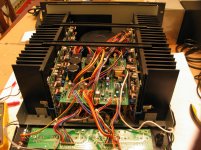
Attachments

Last edited:
I think you are looking at this all wrong. Does the first relay click shortly after the power is turned on? If so that's the big relay, top center of the picture. That's the in-rush circuit relay, common on all amplifiers with a toroid power transformer, the big round thing. The two relays under the big one in the center of the picture are the switching relays for the transformer secondaries, there are switches on the back to choose between 4 or 8 Ohms, correct? Those choose high or low voltage, high for 8 Ohms and low for 4 Ohms. There should be one of those relays for each pair of channels. The two on the right might be two more, follow the wires from the 5 wire connector to left of the relay to see if they go to the transformer. To find the output relays, if any, follow the speaker terminals/wires back to their origin. That's all can tell from the picture.
Craig
Craig
Have a look at this user manual if you haven't already seen it:- http://www.techsourcedist.com/technical_bulletins/bb1265_manual.pdf
This amplifier has a number of features including auto detect of an incoming signal and 'trigger mode' (detects an incoming voltage, presumably so that it can be turned on in synch with other modules when a single switch is thrown or another unit is activated). These modes are controlled by the 'Power Mode' switch. Check that this is set to 'Constant' and read through the other instructions.
This amplifier has a number of features including auto detect of an incoming signal and 'trigger mode' (detects an incoming voltage, presumably so that it can be turned on in synch with other modules when a single switch is thrown or another unit is activated). These modes are controlled by the 'Power Mode' switch. Check that this is set to 'Constant' and read through the other instructions.
Craig -
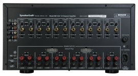
Thanks for the info. Yes, you are correct. There are 4/8 ohm switches on the back for each channel pair. I am amazed you could deduce that from the picture (I am but a weekend hack who likes to fix things). I have added a picture of the back panel. If you look at the other picture of the back of the amp - the board that is laying down (the back) – you can see two sets of small wires crossing just over the outsides of the speaker output wire connecters – these run to the 4/8 ohm switches.
Now, each channel pair has a 5 pin connector coming from the transformer. After taking some readings from it, I was a bit perplexed but I think you just explained it for me. I should have posted them before but didn’t think they were meaningful. The measurements I took of the pins were AC voltage (34V, 27V, N, 27V, 34V). 34V for the 8 ohms setting and 27V for 4 ohms?
Yes, the large relay opens up on power on. So do the 6 smaller ones that are on the transformer side of the boards (left side in pic - you can see only two). The switching relays you called them. What you can see in the picture is the top card that has 2 zones on it (4 channels). There is another card below it with the other 4 zones (8 channels).
I am pretty sure it flows from left to right. The relays that are not opening are on the right side - between the wires that run to the output boards (left of that relay) and the wires that run to the speaker posts (right side of relay). The wires that run to the output board (before that relay) are also 5 pin. If I recall correctly DC (49V, G, -49V, 0V, 0V). I assumed the rails B+ and B-. Would the two without voltage be the output signal back to the speakers? If so would they then be AC?
Attachments
Counter –
Thank you for your link. Yes I do have a copy of the manual, and I do wish it were that simple. The power is flowing just not making it all the way out. There is AC running to that top board that flows to the transformer when the power switch is pressed. The other trigger mechanisms do work also. In the 12V trigger position no power flows until I connect 12V source to the trigger input.
Thank you for your link. Yes I do have a copy of the manual, and I do wish it were that simple. The power is flowing just not making it all the way out. There is AC running to that top board that flows to the transformer when the power switch is pressed. The other trigger mechanisms do work also. In the 12V trigger position no power flows until I connect 12V source to the trigger input.
Since it sounds like multiple channels doing this, my first reaction was missing power supply. You should have high voltage supplies for the amplifiers themselves, plus low voltage supplies for the other parts. You report a lot of the LEDs not lighting, that is consistent with a missing low voltage supply. That is the first thing I would check.
No, the contacts are not welded. I can apply 12V to the relay's coil and it does engage properly.
There are seven LEDS on the face, but six are Fault LEDs, so only one, the Active LED, should be lighted (it is not). Now it is not lighting any of the channel fault condition LEDs which would be normal if the individual channels did not have a problem, which I believe is the case.
Not sure how to verify that the low voltage is working properly. However, one of the connectors at the edge of the upper board does have markings 15V, -15V, G, 10V. These all checked out properly.
I may be barking up the wrong tree, it wouldn't be the first time, but my assumption is that some condition(s) would have to be true for those relays to get 12V to open (and at that time the Active LED also gets powered). On my Parasound amps it would be like it was stuck in the standby mode never getting to active. Something like too much DC offset, but I think that condition would be a channel pair by channel pair condition. Since it is not going into its "Active" state I thought some system wide condition was not being met. Hence back to the original question “what condition would the amp check for before allowing the output relays to open? Which I guess would be some kind of protection circuit?
At the left of the rear panel, I see:
12v control output
audio sense
May be there is something there to condition output relays.
12v control output
audio sense
May be there is something there to condition output relays.
No, the contacts are not welded. I can apply 12V to the relay's coil and it does engage properly.
Do you get output? Activate the relay, check for DC on the output, if it's OK connect up a scrap-box speaker and apply an input. That will tell us something.
Did you have this amplifier working in the past, or did you get it in this condition?
http://www.techsourcedist.com/technical_bulletins/bb1265_manual.pdf
Power Mode Selection
There are three ways to turn the amplifier on and off. Use the following list to
decide which mode will work best for your application.
See Diagram 3
below.
1. Constant
Use this selection when you wish to manually turn the amplifier on
and off by using the front mounted power button.
2. Trigger
Use this selection if you wish the amplifier turn on when it receives
voltage (3-30V A/C or D/C) from an external source and turn off once
that voltage has stopped. Some components have voltage outputs
that are designed for this use. In addition there are devices that can
be used as part of an automated system that will provide voltage to
enable the mode. The voltage source must be connected to the trig-
ger-input jack on the back of the amplifier.
3. Audio Sense
Use this selection when you want the amplifier to turn on when the
amplifier’s main input receives an audio signal. At the moment that
either the left or right input jacks receive a signal the amplifier is
turned on. Once the signal stops the amplifier waits 3 minutes and
then turns off.
The trigger mechanisms do all work. When in the manual position the front switch does work like a manual on/off switch and lets power flow to the transformer when on. Draw jumps from 1W to about 50W. In 12V position it stays off when the power switch on until I give it 12V into the trigger then the Main relay opens and power flows.
Counter-
I have the top board out right now so that I could get to the underside. Getting 12V to one of those output relays when the board in is place and wired again is going to be a bit tricky. No I never have seen this on, it was headed to the graveyard and I picked it up as a learning project to play with.
The main relay is ok, it is not deformed. The side has a reflection of a resistor and diode you might be seeing, or possibly the shadowing on the top.
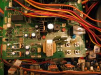
I added a picture of the other side of that top board. That side has the components that are for the whole amp and not the individual channels. The gunk at the base of the caps you might see is glue to hold them down not leakage. The green circular components are NTC thermistors that measure 3.4 ohms. I believe they are for limiting inrush. The only markings they have are SCK 058. They do drop in resistance when heated. I have no clue what the little red disks are yet.
Counter-
I have the top board out right now so that I could get to the underside. Getting 12V to one of those output relays when the board in is place and wired again is going to be a bit tricky. No I never have seen this on, it was headed to the graveyard and I picked it up as a learning project to play with.
The main relay is ok, it is not deformed. The side has a reflection of a resistor and diode you might be seeing, or possibly the shadowing on the top.
I added a picture of the other side of that top board. That side has the components that are for the whole amp and not the individual channels. The gunk at the base of the caps you might see is glue to hold them down not leakage. The green circular components are NTC thermistors that measure 3.4 ohms. I believe they are for limiting inrush. The only markings they have are SCK 058. They do drop in resistance when heated. I have no clue what the little red disks are yet.
Attachments
Last edited:
There's almost certainly a small logic section doing the supervisory functions, probably runs @ 5V, uses a PIC or Atmel uProc, or some chip-level logic, 74xxXXX chips, see if you can identify anything like that. You can get a little pen-style logic driver that will allow you to momentarily overdrive some of the lines without causing damage, useful for debug.
You might have to hardwire an override of some of the safety features to get some functionality, but that would be a partial win.
You might have to hardwire an override of some of the safety features to get some functionality, but that would be a partial win.
Counter-
Most of your last post went over my head, but I think I get the gist. (what is this pen style logic-driver you referenced, I am very curious?) I too was expecting to find an IC to handle some logic considering the myriad of switches/options and channels this thing has. I have yet to find one, but read on…
Gajanan-
Eureka!!!
Those little red disks ARE FUSES. 1 amp 250V 372 series micro fuses to be exact. Refer to my last posted picture - The one that is to the left of the main relay and to the right of the rectifier (above the thermistors) is OPEN. The white connector just above that micro fuse leads back to the toroidal getting power. One leg of that connector leads to one “S” source? leg of that rectifier. The other leg of the connector runs through that blown fuse and then on to the other “S” leg of that rectifier. The missing 12V DC that opens up those output relays must be coming from that un-powered rectifier.
Now I am not going to get too happy just yet. I am fully expecting that when I put a new one in that it blows right away because of some other yet to be resolved issue further in, but at least now I know where to look and can trace it. They are $0.40 a piece so with $5 shipping I bought a few extras.
Enzo-
You were correct all along, missing low voltage power supply.
Now the part I hate, having to wait a week for the part to arrive before I can continue. I will post an update in a few days. Thanks to all again…
Last edited:
Great finding !
“S” source? leg . The S is a symbol to mean AC.
Obviously, the two S legs on the rectifier are its AC inputs, the + and - legs are the DC outputs.
This is perfectly consistent with an S going to the toroidal and the other S going to the toroidal via the ( blown ) fuse.
“S” source? leg . The S is a symbol to mean AC.
Obviously, the two S legs on the rectifier are its AC inputs, the + and - legs are the DC outputs.
This is perfectly consistent with an S going to the toroidal and the other S going to the toroidal via the ( blown ) fuse.
Last edited:
- Status
- Not open for further replies.
- Home
- Amplifiers
- Solid State
- What may prevent Output Relays from opening?