I'm very confused there are 3 legs on the resistor should I connect it to the very ends or one at the end and one in the middle?
Also it says replace R81 for 180r if its too low not to connect to terminals. If its too low then connect 220r to terminals.
Also it says replace R81 for 180r if its too low not to connect to terminals. If its too low then connect 220r to terminals.
Having studies the SM religiously I managed to figure out there is no A - B resistor but in fact its talking about the one resistor i.e one outer leg and one inner leg. With great difficulty managed to find A side and so far its testing nearly 10mv after 7-10 minutes on left side (blown channel) and right side measure 17mv. I'm guessing something is wrong with the left channel
Last edited:
Bit strange...either the transistors needed wearing in or I fixed it!
I read the manual about the bias transistor and decided to swap them around to identify if it was faulty. It lies between the output trans. It wasn't faulty and now both channels after 20 min+ on are left around 11.5-12.5mv and right 12.5-13.5mv.
I'm not sure how much of a difference 1mv makes to channel separation!?
If its not a big issue I'm going to box it up and send it to my buddy 🙂 needless to say I will be bragging to him about my fix LOL.
Hi dj_holmes,
You probably corrected a bad solder joint.
In general, you really don't want to swap components between channels. It's a great way to end up with two misbehaving channels instead of just one. In future, don't do that.
When you test an amplifier if you want to flick it on (bad idea), make sure there are no speakers attached - or any other load for that matter. With a DC offset you can get high current flow. Destructive to speakers.
Components can blow in msec, which is a lot faster than 1/2 a second. That's probably shorter time than you had the power on. That's why you should use either the "light bulb tester", or better yet, a "variac" (variable AC transformer). The variac allows you to control the voltage and energy allowed into the unit under test. It also allows you to troubleshoot at reduced voltages. It makes your life a lot easier.
-Chris
Nice going DJ, so far so good. Bias current doesn't affect channel separation but it does minimise crossover distortion in class B and AB amplifiers. This is the unavoidable glitch in the transfer of output current, alternately from upper and lower output transistors, with each transition from upper to lower half of the audio output waveform, diagramatically speaking, at least.
Unfortunately, crossover glitches are an inherent flaw in all class B and AB amplifiers but you'll find that small differences in the bias current used to minimise distortion, like 1mV, make no odds really. It's only if it's more than 10% different from spec. that you might adjust it here.
Bias current settings are essentially temperature dependent so the "bias transistor" is there to compensate for this as the amplifier warms then cycles hot and cold with variations in power level but when you open the case and the temperature of the transistor suddenly drops, the bias setting will change and no longer be in synch. with the output transistors temp. It's likely this lag in thermal equilibrium was different when you measured the current on each occasion.
This difference in measurements makes it necessary to follow adjustment procedure to the letter. Even so, soak test over a couple of sessions to be certain all remains good before sending it to your friend. If settings don't remain stable, the freight costs to fix it will be become an even bigger problem.
For interest, a pic. here of Cyrus 1 with space for 2 sets of power transistors as you mentioned but something I'd not seen: File:MissionCyrus1-2.JPG - Wikimedia Commons
Well done in getting it up and running 
The bias 'question' cropped up in the thread I linked to earlier. Fixed bias schemes depend critically on the exact device parameters used in production. Modern semiconductor replacements will differ due to different manufacturing processes and doping techniques.
If the bias is in the correct range now, then leave well alone. I assume you are measuring the voltage across the 0.22 ohms in order to derive the current, and not the voltage on the 0.22 ohms which is totally unrelated to bias.
Thanks for all the comment!!
I need to build one of those bulb safety device s for sure! But I was pretty certain it would be ok! It was just a little project for a friend. If I was keeping it or problem was more serious I wouldn't have taken the risk.
Yes even my Cyrus had space for more transistors! Even had the tracks for external power connector! I believe it's essentially the same board as Cyrus 2!!
Mooly I read your thread again for bias. But the measurements were so small that I thought that it would be ok rather than spend numerous hours changing resistors. I didn't fancy unsoldering the switch and PSU cables again!
I've got another project more complicated coming up. Hopefully tomorrow that I will for certain need help on in a new thread.
I tested the Cyrus for over an hour yesterday and it sounded really good. Believe the hype! DC offset was under 10mv each channel when initially tested!
Thanks again guys!
Oh and yes I measured on 2 of the 3 legged resistor 0.22 ohms. The side that should be A. Thanks
Hi dj_holmes,
Yes, the three legged resistor is just a pair of resistors together. Those are called "plate resistors" and have very low inductance. You measure across the outside pair, giving you 0.44 ohms. Bias current is approximate and changes with temperature, so don't worry about any exact value. The two channels don't have to match, but yours do. As mentioned earlier, bias current primarily reduces "cross-over distortion" as the current flow passes from one transistor to the other. There is no effect on gain.
This repair turned out very well. Those amplifiers are known to sound good, and now you know that from experience.
My earlier comments were not a comment on you or your work. I'm trying to keep you from developing bad habits, that's all.
Best, Chris
Thanks!! Happy it was that simple.
All the comments good or bad was helpful! Better safe than sorry at the end of the day!
The next project won't be! But I'm dead keen on its more high end, new thread hopefully tomorrow.
Thanks again for all the help!
All the comments good or bad was helpful! Better safe than sorry at the end of the day!
The next project won't be! But I'm dead keen on its more high end, new thread hopefully tomorrow.
Thanks again for all the help!
thread hijack apologies ... very early cyrus 2 question !
(sorry, if this question would be better as a fresh post, I'll do that if you think it better.)
I've acquired a very early cyrus 2 and I've replaced all the electrolytics apart from the big 10000uF supply caps.
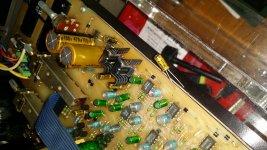
what's odd is that unlike any other cyrus I've seen there's no polarised 22uF cap where c71 would be. i say would be, but this cyrus is so old it has wired on/off switch and no markings on the circuit board ie it doesn't actually say c71 on the board or anything else for that matter. There's holes where I'd expect a cap and there's solder traces , whereas other empty / unused holes on the board have bare copper.
I can't find either a cyrus 2 service manual (i have a cyrus 1 circuit diagram) or even a photo of any cyrus 2 this old.
see pic ... (I've marked the spot in question with a new cap for the pic)
(sorry, if this question would be better as a fresh post, I'll do that if you think it better.)
I've acquired a very early cyrus 2 and I've replaced all the electrolytics apart from the big 10000uF supply caps.
what's odd is that unlike any other cyrus I've seen there's no polarised 22uF cap where c71 would be. i say would be, but this cyrus is so old it has wired on/off switch and no markings on the circuit board ie it doesn't actually say c71 on the board or anything else for that matter. There's holes where I'd expect a cap and there's solder traces , whereas other empty / unused holes on the board have bare copper.
I can't find either a cyrus 2 service manual (i have a cyrus 1 circuit diagram) or even a photo of any cyrus 2 this old.
see pic ... (I've marked the spot in question with a new cap for the pic)
Attachments
Last edited:
Hi I'm no expert. I did what I could to help! 🙂
Oh sorry file too big go to
Cyrus 2 - Manual - Stereo Integrated Amplifier - HiFi Engine
Oh sorry file too big go to
Cyrus 2 - Manual - Stereo Integrated Amplifier - HiFi Engine
thanks for the link , I've half a chance with a cyrus 2 service manual ! thank you, I only found a cyrus 1 service manual before so that really helps.
amazing that I can't even find a photo of a 2 as early as this one with no board markings, must have been interesting fixing them back in the day with an unmarked board ....I have to say the soldering on this one is worse than mine ! mission/cyrus might not have changed the basic circuit over the years but the build certainly got better. Having said that , the plastic covers hold up well compared to the later nextel covered cast ones, and it's handy that you don't have to mount/unmount the output trannies from the heatsink every time you want to lift the board or test it with the earth reconnected. Plus the early ones have bias adjustment presets fitted and an electrical on/off switch rather than the plastic linkage thing that generally broke ...
cheers !
and yes Mooly I am back for more. The cyrus one you helped me fix 4 months ago putting in sterling service at my niece's place and my brother's 06 cyrus 2 running well too. This one is going to a mate's in wales who has a big room and needs the extra wallop this'll have 🙂
The missing cap looks like it connects to the diodes nearby ?
That suggests either some rail decoupler or perhaps something to give a time constant to minimise switch on/off noises.
If its not been fitted from new then it is that way for a reason. Fwiw, it is common to see blank component spaces and various used/unused 'options' on PCB's.
That suggests either some rail decoupler or perhaps something to give a time constant to minimise switch on/off noises.
If its not been fitted from new then it is that way for a reason. Fwiw, it is common to see blank component spaces and various used/unused 'options' on PCB's.
and yes Mooly I am back for more. The cyrus one you helped me fix 4 months ago putting in sterling service at my niece's place and my brother's 06 cyrus 2 running well too. This one is going to a mate's in wales who has a big room and needs the extra wallop this'll have 🙂
I noticed 😉 Pleased to hear the other amp is running well.
not seeing a c71 on the 06 version parts list , interesting that issue 07 does have that, and odd that something there's mounting holes there and signs that something was once fitted there, wonder what c71 does and if it would help an 06
Thanks Mooly, yes there are other unused mounting holes, was just intrigued that this pair looks like there has been something fitted there, and that every other cyrus I've seen has had a 22uF between those two tracks. Anyway it sounds good and I still need to restore the main switch, so really I'm just being greedy while I'm in here with a soldering iron and have a bag of nice caps , rank amateur that I am. This one hasn't got the slit foil main supply caps they later fitted, not sure how much of an improvement they are, or if the volume switch could use an upgrade ....
as an aside does anyone know what the barrel shaped light blue capacitors in the pic are ? all the other cyrus I've seen have had green box shaped (film?) caps. Hope fully these stay in spec and are as good, but can't help wondering why they stopped using them.
C71 appears to be on the output of the LM317 reg (07 version) and is C68 in the 06 version. So both versions seem to have it, at least on the diagrams.
You would normally have a cap on the output of a regulator (although for the LM317 it is optional) and normally it would be a small value in the 1uF to 47uF range.
There can be valid reasons for having unequal values of cap between the rails or having no cap at all, and those reasons would be related to start up behaviour (the fixed 78/79 series regs can latch up if one rail appears before the other) or it may be to minimise audible noise during power up.
If you think one has been fitted and then removed by someone then you could try a small value polarised type.
- Status
- Not open for further replies.
- Home
- Amplifiers
- Solid State
- What makes a good output transistor for Cyrus One