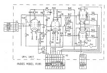
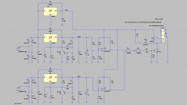
Pentode Amplifier (V1) driving a common cathode triode amplifier with direct coupled comcertina (cathodyne) phase splitter (V2) and push pull output tubes (tetrode connected).
The OUT2 and OUT1 connections are the feeds to the push and pull sides of the output transformer.
The NFB (Negative Feed Back) connection comes from the secondary of the output transformer (with other side of secondary going to earth)
The Output Tubes are new to me. The first tube is a bit of a mystery - all those shields on pin 2 and 7 (check EF86??), the common cathode/concertina splitter dual triode may be a 6SN7 (correct pin numbers).
It would seem to have a lot of gain so probably ran a lot of feedback to get a low output impedance (good damping factor).
Just my thoughts - from a quick look.
Cheers,
Ian
The first tube is an EF86, the second an ECC85 or ECC88 (probably the latter). The power tubes I cannot find right now but I have seen them somewhere. I think they are some of these high power sweepers found in tv sets. Impressive for high power amplifiers but their transconductance can be a bit varying.
Unasked advice: Don't put this circuit high up on your list of future projects - one could do better with the twin triode as a Schmitt phase inverter directly coupled to the EF86, and tetrodes or pentodes in the power stage for high fidelity is not a good idea. Sorry.
Unasked advice: Don't put this circuit high up on your list of future projects - one could do better with the twin triode as a Schmitt phase inverter directly coupled to the EF86, and tetrodes or pentodes in the power stage for high fidelity is not a good idea. Sorry.
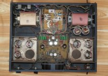
It's an old Soviet time amplifier more know by the name of "Briboy" Audes also used to build them. During the years there has been numerous modifications made by several Russian hobbyist to make it sound better. While the output iron, output and driver tubes are good, the first modification would be to change the input gain tube and all the old capacitors.
Do you own this amp or intend to build from scratch?

Do you own this amp or intend to build from scratch?
I got my hands on one in 1996/97 but after a output tube imploded i forgot about it until now, i didn`t know how it was build or how to read the schematic but i`m modifying it right now with Mundorf capacitors to see if it`got any pontential at all.
So far so good 🙂
So far so good 🙂
:d seams an old therd but:
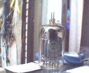
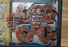
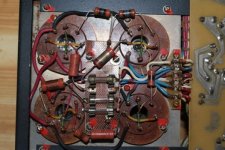
first of all, get rid of thse 6Р3С (latin 6r3s) they are really unstable (u can't leave the amp un and not wach it - tubes tend to overheat and then melt, as well revire heating in paralel to be more stable). Aftre few week I will get one amp, and now I'm looking for altrenate schematic.
tbes are 6Ж32П (EF86), 6Н6П (I don't know analog, close mach would be 6AH4-GT, ECC88 could do but you have to redo the shematic then)
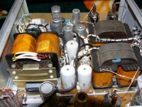
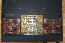
in attachmetnt is russian "Прибои" (latin "Priboi") inside picture. I'll poste wholl schematic as well. they had two versions 50W and 75W (only diference is in Plate supplay voltages).
first of all, get rid of thse 6Р3С (latin 6r3s) they are really unstable (u can't leave the amp un and not wach it - tubes tend to overheat and then melt, as well revire heating in paralel to be more stable). Aftre few week I will get one amp, and now I'm looking for altrenate schematic.
tbes are 6Ж32П (EF86), 6Н6П (I don't know analog, close mach would be 6AH4-GT, ECC88 could do but you have to redo the shematic then)
in attachmetnt is russian "Прибои" (latin "Priboi") inside picture. I'll poste wholl schematic as well. they had two versions 50W and 75W (only diference is in Plate supplay voltages).
and the full schematic is found here, I hope the link works http://www.eserviceinfo.com/download.php?fileid=17696
I searched for a hybrid amp with tubes 6r3s-1
I have not found such a post in this forum
I got this amp. This is PA 500.
I opened the tin box and began to draw its electrical circuit.
There are 3pcs. 6R3S-1; 6N6P; KP574UD2A /dual operational amplifier with field effect transistors/ for each channel.
I took measurements to determine the modes of the final step in 6P3S-1.
Anode voltage is 600V for the 6R3S-1.
Ug1 =- 45V, and is fixed by a resistor voltage divider. Trimer is not installed, which is necessary to equalize the initial cathode current.
I measured the voltage drop of 6 cathode resistors. He was in a range of 0.1 to 0.18 volts.
Urcathode0=(0,1 – 0,18)V
Rc=10ohm
Icathode0=Uc0/Rc
Ic0=(0,1 – 0,18)/10
Ic0=(10 – 18)mA.
Under these initial conditions the operation mode is class AB push/pull, with an initial cathode current of 10-18mA
I am ready to publish a sketch of the block diagram of the amplifier.
![22663_103387913021856_100000519437632_90565_7945165_n[1].jpg](https://www.diyaudio.com/community/data/attachments/158/158961-07c93a6f441b9be51345f5376f370375.jpg?hash=B8k6b0Qbm- "22663_103387913021856_100000519437632_90565_7945165_n[1].jpg")
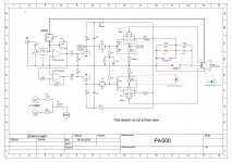
Setting the parameters of the PA500 amplifier.
This is a variant of the bridge connecting the speakers (6 tubes), it has three tubes per channel.
I'm interested in stereo option.
I will use only four tubes.
1. In the beginning I started measuring the number of six cathode resistors Rcathode=10ohm.
2. I measured the currents of six end tubes (VL1-VL6), as a voltage drop on the cathode resistor, for Ua = 600V, Ug1 = - 45V.
VL1 ... 5.7mA;
VL2 ... 4.2mA - fell;
VL3 ... 16.2mA;
VL4 ... 8.6mA;
VL5 ... 14.0mA
VL6 ... 11.7mA.
3. And arranged in pairs:
For the Left channel
VL1…5,7mA;
VL2…disconnected of cathode fuse;
VL3... 8,6mA;
For the Right Channel
VL4…16,2mA;
VL5…disconnected of cathode fuse;
VL6…14mA
But ... the sound does not change.
This amp is not working properly.
High THD.
4. I found a new 6P3S-1 and placed as VL2:
VL1 ... 5.7mA;
VL2 ... 50.5mA;
VL3 ... 8.6mA;
VL4 ... 16.2mA;
VL5 ... 11.7mA connected of cathode fuse;
VL6 ....14.0mA.
5. I decided to change the cathode current of each channel 50mA, by changing the grid voltage.
5.1 ………......Ug1 = -37.7 V for the L channel.
5.2 …………..Ug1 = -39.4 V for the R channel.
5.3 I measured the new values for cathode currents:
For the Left channel:
VL1…45,6mA;
VL2…disconnected of cathode fuse;
VL3... 46,6mA;
For the Right Channel
VL4…52,7mA;
VL5…disconnected of cathode fuse;
VL6…49,2mA
Improve the sound.
Gentlemen, do you think I did everything correctly?
I will be glad of any assessments. Thank you.
acarp
Attachments

Yesterday I checked cathode currents of pA500.
After 4 hours of work:
VL1 ... 41.3mA
VL2 ...
VL3 ... 41.4mA
VL4 ... 46.5 mA
VL5 ...
VL6 ... 49.2 mA.
Here are some pictures
After 4 hours of work:
VL1 ... 41.3mA
VL2 ...
VL3 ... 41.4mA
VL4 ... 46.5 mA
VL5 ...
VL6 ... 49.2 mA.
Here are some pictures
Attachments
.It's an old Soviet time amplifier more know by the name of "Briboy" Audes also used to build them. During the years there has been numerous modifications made by several Russian hobbyist to make it sound better. While the output iron, output and driver tubes are good, the first modification would be to change the input gain tube and all the old capacitors.
Do you own this amp or intend to build from scratch?
This is Soviet Union (Russian) tube power amplifier, named "Priboy" or "Priboj" or "Priboi".
.
If somebody wants, i shall put here full circuit of this power amplifier and photo of this device.
In Russia this power amplifier is costs about 10000 rubles (300$ - 350$).
.
- Status
- Not open for further replies.
- Home
- Amplifiers
- Tubes / Valves
- What kind of amp?