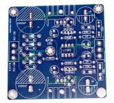
I have this pcb that I got off ebay for a few bucks.
I'm building a preamp and I need a -15/+15v supply for it.
The schematic they included in the listing has slightly different resistor values compared to the ones on the pcb because it is for a fixed output. This is actually how I plan on implementing it. The board also allows for an adjustable output using trimpots.
Only thing that has me scratching my head is the LF353 opamp. What is the function of this? Does it keep the outputs equally symmetric?
Can I safely leave this out of the design? Or is it recommended I leave it in?
Attachments
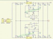
Yes, it is an opamp denoiser; it is also wired for a correction factor of ~30dB.
The advantage of an opamp is more convenient coupling capacitors values, the disadvantage is that the noise will be higher: you need a very good opamp to match a very cheap transistor like the BC337, and no opamp will match a transistor like the ZTX851.
But the circuit should work OK, and improve the PSRR and the output Z
It is a dual LDO regulator with an opamp de-noiser. At $10.80 fully assembled, it is one of the best PSU board deal on e-bay.I have this pcb that I got off ebay for a few bucks.
I'm building a preamp and I need a -15/+15v supply for it.
The schematic they included in the listing has slightly different resistor values compared to the ones on the pcb because it is for a fixed output. This is actually how I plan on implementing it. The board also allows for an adjustable output using trimpots.
Only thing that has me scratching my head is the LF353 opamp. What is the function of this? Does it keep the outputs equally symmetric?
Can I safely leave this out of the design? Or is it recommended I leave it in?
The LF353 a good choice for its function. It is on socket and can be esaily changed if so desired.
AC-DC LM317 LM337 LF353 Servo Rectifier Filter Power Supply Module Adjustable M | eBay
But it is NOT a 1.5A output board. The heatsink should be fine for a class A line level or headphone amp biased at 200mA or so, but not much more.
Last edited:
The 2x5K trimmers give the board pretty good range for output voltage adjustment. Set the trimers at 2K2ohm if you want 15 volts outputs.I may (be) wrong but calculating the output voltage remains the same:
(2k2/200R +1)*1.25 =15V.
Last edited:
My local electronics component seller didn't have the LF353 in stock. It appears to be an obsolete opamp. Can I replace it for a NE5532?
There are many equivalents, TLO72, 82 and many others.
The 5532 could work, and would have a better noise performance, but there is a risk of instability. The compensation cap might need to be adjusted
The 5532 could work, and would have a better noise performance, but there is a risk of instability. The compensation cap might need to be adjusted
LF353 was commercially replaced by similar but cheaper TL072, which your store sure should have. The '353 is still available, and costs only pennies more, but nearly all the early 1970s stuff that started on LF353 moved over to TL072, often as a drop-in, often without noting this on the docs.
'5532 "should work" and maybe less hiss but probably too little difference to tell.
'5532 "should work" and maybe less hiss but probably too little difference to tell.
LF353 was commercially replaced by similar but cheaper TL072, which your store sure should have. The '353 is still available, and costs only pennies more, but nearly all the early 1970s stuff that started on LF353 moved over to TL072, often as a drop-in, often without noting this on the docs.
'5532 "should work" and maybe less hiss but probably too little difference to tell.
Thanks for the information! I already went for the TL072 so I' m glad it was the right choice
TL072 and LF353 are both JFET input opamp and often considered interchangeable. The smaller bandwidth of the TL072 should not be a problem for a denoiser servo.LF353 was commercially replaced by similar but cheaper TL072, which your store sure should have. The '353 is still available, and costs only pennies more, but nearly all the early 1970s stuff that started on LF353 moved over to TL072, often as a drop-in, often without noting this on the docs.
'5532 "should work" and maybe less hiss but probably too little difference to tell.
The NE5532 is bipolar input opamp and lower noise. What does that mean to the denoiser servo application?
The input impedance is totally irrelevant in a denoiser application, and in fact the gain resistors around the 5532 should be lower, to take advantage of the better noise performance, and reduce the effect of the noise current.
I didn't make any calculation, but you can safely go to very low values since the signal handled is normally quite low.
Properly using a 5532 will lower the noise floor compared to a TLO72, but an ordinary transistor will do even better
I didn't make any calculation, but you can safely go to very low values since the signal handled is normally quite low.
Properly using a 5532 will lower the noise floor compared to a TLO72, but an ordinary transistor will do even better
Thank you for your advise. I have tons of NE5532 replaced by LME49720 (in line amp and active crossover). It comes handy for the denoiser PSU.The input impedance is totally irrelevant in a denoiser application, and in fact the gain resistors around the 5532 should be lower, to take advantage of the better noise performance, and reduce the effect of the noise current.
I didn't make any calculation, but you can safely go to very low values since the signal handled is normally quite low.
Properly using a 5532 will lower the noise floor compared to a TLO72, but an ordinary transistor will do even better
Unbalanced voltages
I need +5v and -15v. Can the LF353 operate on an unbalanced supply and still do denoising?
I need +5v and -15v. Can the LF353 operate on an unbalanced supply and still do denoising?
I haven't looked at the cirquit but opamps usually don't need balanced supply at all.I need +5v and -15v. Can the LF353 operate on an unbalanced supply and still do denoising?
- Home
- Amplifiers
- Power Supplies
- What is this opamp doing in this power supply schematic?