Hello,
i got my hands on a class d amplifier schematic with pcb and all.
but the documentation is all in German.i translated that to English using machine translation(pain in ***,took a good four hours),but still documentation is difficult to interpret.
one component in the pcb cant be identified properly,i am attaching the image,can anyone tell me what is it?(air core inductor????)
Attachments
Can you take a pic of it ? I´d say its the footprint for the amps output filter inductors, but i could be wrong.
hi Tekko,
>>>> Can you take a pic of it ? <<<<<,,i didnt get u on this count.
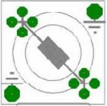
the amplifier pcb is double sided, it is the o/p inductor but what baffles me is the total number of green dots. I am attaching the image.
Hi danko
it is the inductor but what r the various green for.An inductor has two terminals,but here ,,going above my head
BTW,do have its translated version so life can be simple for me,🙂
>>>> Can you take a pic of it ? <<<<<,,i didnt get u on this count.
the amplifier pcb is double sided, it is the o/p inductor but what baffles me is the total number of green dots. I am attaching the image.
Hi danko
it is the inductor but what r the various green for.An inductor has two terminals,but here
,,going above my headBTW,do have its translated version so life can be simple for me,🙂
Attachments
Indeed.
It is probably an RM core. The two sets of four pads are for the pins on the bobbin which the wire is wound on and the other two pads are for the metal clips that hold the two core halves together.
http://www.ferroxcube.com/prod/assets/rm_frnt.pdf
It is probably an RM core. The two sets of four pads are for the pins on the bobbin which the wire is wound on and the other two pads are for the metal clips that hold the two core halves together.
http://www.ferroxcube.com/prod/assets/rm_frnt.pdf
I don't see why not..... however,
Once gapped the ferrites used in things like RM and POT cores are extremely linear up to saturation.
The materials used in toroids are usually an 'exotic' mix of nickel manganese and iron powder used to achieve a high saturation flux density with reasonable losses.
They are really targeted at low cost SMPS output filter applications where the ripple current, and resulting core losses, is substantially smaller than the DC current. A class D amplifier might have significant ripple current in the output filter inductor.
One of the things they do is 'soft saturate'. It means that you might design for a particular zero DC bias value but you have to accept that the operating inductance with a DC current will fall, perhaps up to 50%, 40uH might go down to 20uH.
You might account for that in your design and in an SMPS it's not necessarily a major concern. However for a class D amplifier that sort of behaviour might be unacceptable.
I wouldn't like to comment on the effects on percieved sound quality.
DNA
DNA,
i dont have any problem in using the said inductor but its subject to its availability at my local supplier.
the schematic shows the use of four such inductors,the values are 11.4845uh and 16.241uh.Can u suggest the which one to use Rm5,Rm4,Rm8 or what?what should be number of turns of what thickness wire to achieve these values of inductances?
i will go to market soon to get these if they are available.
Ahh.... two inductors, this is the fourth order one....
The values you give are a little bit too precise but I wouldn't be overly concerned. Just don't expect to do better than 11u5 and 16u or there about.
It's a little bit messy but have a look at....
http://www.genomerics.org/inductors/inductors.html
That might give you some idea about how to get an answer. Unfortunately it's unfinished and does not strictly apply to Class D
amplifiers.
If you give me the values of the capacitors used in the filter, your topology (half bridge, full bridge), supply voltage and target output power or load impedance I can have a fiddle about and suggest a couple of designs...
It would be good to have a complete picture of the output filter including any damping or zobel networks. The first inductor is going to have the highest ripple and will therefore suffer the greatest losses.
DNA
its not mine at all.its from a German website
i am posting the link
http://stud1.tuwien.ac.at/~e0326790/projekte/klassed/klassedde.htm
there are two files for download,one is documentation and other is the pdf for boards.
i am posting the link
http://stud1.tuwien.ac.at/~e0326790/projekte/klassed/klassedde.htm
there are two files for download,one is documentation and other is the pdf for boards.
Oh..... right.
I know it's in German but the information is in the documentation. I suppose if you don't know what to look for then it might be hard to spot and it is 'incomplete'. There is also a mistake.
"Die Berechnung der Spulen für den gewählten Kern vom Typ RM10 ist in Abbildung 22 zu finden."
"The computation of the coils for the selected core of the type RM10 is to be found in illustration 22."
He gives the number of turns as 8.06 and 6.78 and the core is an RM10 with an Al value of 250nH. The Al value is related to the core gap and 250nH is a standard figure that is available from the manufacturer. If you can get hold of them, otherwise you have to add the gap yourself.
The resulting inductance is L=Al.N^2. Unfortunately you can only have integer turns so using 8 and 7 gets you 16uH and 12.25uH. Those values don't hurt the filter response too much........
But the equation he uses to find the allowed peak current is wrong. He gives
B = uo.ur.N.I/2.Le
It should be
B = uo.ur.N.I/Le
If you are going to use the layout provided then your 'stuck' with RM10 cores. Another, better/different, sum is
N = L.Ipk/Bpk.Aemin
The supply is 70V so with a 4R load peak current is 17.5A. That ignores ripple current which he gives as 3.6A peak to peak or 1.8A peak. That will apply to the 16uH one, it sees most of the voltage swing..... Call it 20A worst case.
Using Bpk of 250mT (it is greater than this but it gives you some safety margin) and Aemin of 89mm^2 gives the number of turns for each inductor as... 14.59 and 10.31. You'll end up using 15 turns and 10 turns.
The nominal Al value works out to be 76.29nH. That is not available as a standard value, it's going to be quite a large gap. Using my automagical spreadsheet thing the required gap is 2.82mm.... That is going to be wrong but it's a starting point.
The biggest standard gap is 1mm, that's for one core half. If you took a pair then you would get 2mm, which isn't enough. That gap is in the center leg. If you buy an ungapped core set and space to two halves apart then you place a gap in the center and outer legs so you need 1.4mm for a total of 2.8mm.
Like I say, it's a big gap so you might find the clamping pins are a bit overstretched...... No matter, never mind. Again the actual value you get won't be right so it might need adjusting. If you have an inductance meter or any suitable test equipment then it makes life a little bit easier.
Anyway. If you can get it then you might find that copper foil is going to be the best choice for implementing the windings. Otherwise wire will do the job. It just so happens that the link I gave you uses an RM10 for the example so the mechanical information for the bobbin is somewhere on there. There is also a table of wire sizes.
You can use that lot to work out what sort of wire is going to fit and buy some of it.
In this case the ripple currents are relatively low so you should not have to worry about AC core and copper losses. The core material shouldn't be too critical either. The actual low frequency copper loss might be high but....... it's music so you should get away with it.
Hope that lot made sense.
DNA
Hi guys
Hi guys!
Since the Document you're talking about was written by me, I thoght I could contribute abit to the discussion.
You're right the calculations are wrong. Thank you very much for saying that. I was always wodering why the amp was shutting down when I was taking too much power! I guess this might be a reason.
If you're searching for R10 cores. I found some on RS-Components, that could be compatible. Unforunately Pinouts are not the same: RS code: 228-242. The originals have been discontinued, or at least I can't find them anywhere.
I will look arround, maybe I'll be able to find my original drawings, so if you like you can change the Cores, and use others instead of the RM10.
Greetings from Vienna!
Simon
Thanks for coming along. Sorry I should have e-mailed from the original web page.
If that is the reason, inductor saturating, then you must have some good protection in the amplifier.😎
Nice documentation..😉
DNA
If that is the reason, inductor saturating, then you must have some good protection in the amplifier.😎
Nice documentation..😉
DNA
Hi Genomeric
Thanks for extending your time and help else i would have gone along with wrong calculations.When one doesnt know what to look for(in my case a core called RM10 ),it becomes difficult to find out the info.
i consulted Mr Simon himself regarding the amp and your pionting out of the error in formula used.He came here to sort it out.Thank u Simon.
.i had planned to go for buying these,thankfully this revelation about cores' discontinuance came at the right time.
As the core is now discontinued,so what else can be the alternative?
Thanks for extending your time and help else i would have gone along with wrong calculations.When one doesnt know what to look for(in my case a core called RM10
),it becomes difficult to find out the info.i consulted Mr Simon himself regarding the amp and your pionting out of the error in formula used.He came here to sort it out.Thank u Simon.
.i had planned to go for buying these,thankfully this revelation about cores' discontinuance came at the right time.
As the core is now discontinued,so what else can be the alternative?
If it is really really and RM10 core and it really looks like it is then the core sets themselves are widely available. I think the problem might lie with availability of the particular bobbin (coil former) that the PCB footprint has been laid out for.
Having said that if I look in an 'old' data sheet a 12 pin bobbin is available and all you have to do to fit it to the PCB is chop off the unused pins.... hang on,
Have a look at
http://www.ferroxcube.com/prod/assets/rm10i.pdf
From
http://www.ferroxcube.com/
That's current.
Really the remaining issue is availability of something with the right gap size. Unfortunately, unless you are a bulk buyer you might not be able to get gapped cores and will have to do it yourself anyway.
Hmmmmm, Here we go....
http://uk.farnell.com/jsp/endecaSearch/partDetail.jsp?SKU=178920&N=401
And
http://uk.farnell.com/jsp/endecaSearch/partDetail.jsp?SKU=3056843&N=401
But that shows as waiting delivery. An alternative is...
http://uk.farnell.com/jsp/endecaSearch/partDetail.jsp?SKU=3110072&N=401
And all the bits are listed on
http://uk.farnell.com/jsp/endecaSearch/searchPage2.jsp?Ntt=RM10&Nty=1&N=401&Ntk=gensearch
DNA
Core availability will not be an issue if these are widely available.but getting the bobbin might be bec i dont have any source for that unlike for core whose seller is a very helpful guy, more than ready to help out students and diy'ers alike.
so that means i should go for buying these cores,but in case bobbin is not obtained would it be feasible to use cores without the bobbin?
in worst case if i dont get eother then what can be the alternative(its important bec the e market is 30km one sided from my place)
so that means i should go for buying these cores,but in case bobbin is not obtained would it be feasible to use cores without the bobbin?
in worst case if i dont get eother then what can be the alternative(its important bec the e market is 30km one sided from my place)
Ahaaaaaa
So, fair enough I'm in the UK but I go and have a look at RS Components which gets me this
RS Components RM10
Now that link might not work(?) but it is an RM10 Core/Bobbin set in F44 material.
You have to get hold of a suitable material. Ferroxcube would be 3C80/3C85/3C90 and Epcos would be N27/N67/N87. A google search tells me that this is a Neosid material. So I go and try to find their website and it turns out that they became part of the MicroMetals group who are now part of the TT Electronics group.
Don't you just love this stuff?
That gets me to
TT Mmcg
And......... from that page there is.....
Ferrite Catalog
It just so happens these people have representatives in India.😱
MMG India Pvt Ltd
144, Seevaram,
Thoraipakkam,
Chennai - 600 096,
INDIA
Tel: +91 44 24965981
Fax: +91 44 24960986
Web:http://www.mmg-india.com
Email:sales@mmg-india.com
Now the Indian website is a little bit broken but the local one lets me download a nice catalog.... (Watch out, it's a big one)
MMG Ferrite Catalog
And this F44 material will probably do the job for you, the power loss curves don't look too bad.
So, there you go. All you have to do is send the Indian Office a nice grovelling e-mail explaining who you are and what you are trying to do and ask if they can post you some bits and pieces. That'll save going to the market.
It'll be worth your while trying to nail down some part numbers.
Give as much information as possible, offer to pay and they might send you some free stuff........ Well, it doesn't always work that way but it's worth a go.
Cheers
DNA
Hi DNA
you have posted something really to cheer about.I will try my luck with that idea of yours.But chances are low for they will have to courrier me and we live on diametrically opposite ends of India.anyways i will try nut BTW i will have to go to that place to arrange for HIP4080 as its not available with the local supplier.
i will enquire and buy any one on which i can get my hands on with preference for RM10 with bobbin,
Thank you for all the good work of yours that you have extended to me.i will keep the developments posted out here.
Sagar
HIP4080
Hey Sagar!
I recently got 5 HIP4080A from Intersil as Samples!
Try to get to they'r Website, and try! The HIP's are normaly quite expensive, so you can save money!
(And bee shure you get the A and not the normal ones!)
The same is valid also for the LM318, only, that I cant remember the Manufacturer!
Greetings! Simon
- Status
- Not open for further replies.
- Home
- Amplifiers
- Class D
- What is this in a Class D amplifier?