Well, remember that low mu triodes have higher feedback intrinsically. High mu triodes can have the same feedback applied externally to reduce the mu to the same value, and generally the result is better linearity.
I've heard people mention intrinsic feedback but have never heard or read a satifactory explanation nor can I see what the path is. Sure, you can add external feedback to a pentode to mimic a triode's characteristic curves but does that really mean that triodes have greater internal feedback?. In real world applications, low mu tubes don't necessarily have lower distortion. Distortion actually varies more with the purity of the materials used in construction than with grid pitch.
John
No, but the quality of materials used is probably the main difference between the Russian GU-50 and the Telefunken LS-50. 🙂
John
John
No, but the quality of materials used is probably the main difference between the Russian GU-50 and the Telefunken LS-50. 🙂
I envy you. I would be glad to have a box of LS-50 to compare. 😀
I've heard people mention intrinsic feedback but have never heard or read a satifactory explanation nor can I see what the path is. Sure, you can add external feedback to a pentode to mimic a triode's characteristic curves but does that really mean that triodes have greater internal feedback?. In real world applications, low mu tubes don't necessarily have lower distortion. Distortion actually varies more with the purity of the materials used in construction than with grid pitch.
John
Try this article by Stockman:
http://ken-gilbert.com/images/pdf/Inherent_FB_inTriodes.pdf
Last edited:
"If grandma was grandpa she should have ..." (C) 😀
Merlin:
Here is my answer to your question "who encouraged the use of DHTs in amplifiers after 1940".
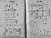
The attached is page 106-107 of the Marconi-Osram Valve Manual, 1951 edition.
The wording (eg "choice of rectifier" [in your amplifier design]) clearly shows that the PX25 is being promoted for design-in in the 1950s, regardless of the production stability of the KT66. The Marconi-Osram Valve company were quite aware that the KT66 (6L6) was not good enough for all designers, however much feedback is applied.
And no wonder. On the facing page you can see the superb characterisation of the PX25 - if anything, even better than the 300B, and linear all the way up to at least 700V.
Notice, too, how the Design Suggestions on this page show fully Open-Loop circuits (zero global negative feedback if you prefer). No feedback is required, because of the high performance of the device.
Another outstanding Directly Heated Triode, still bearing a fully justified fame.
Here is my answer to your question "who encouraged the use of DHTs in amplifiers after 1940".
The attached is page 106-107 of the Marconi-Osram Valve Manual, 1951 edition.
The wording (eg "choice of rectifier" [in your amplifier design]) clearly shows that the PX25 is being promoted for design-in in the 1950s, regardless of the production stability of the KT66. The Marconi-Osram Valve company were quite aware that the KT66 (6L6) was not good enough for all designers, however much feedback is applied.
And no wonder. On the facing page you can see the superb characterisation of the PX25 - if anything, even better than the 300B, and linear all the way up to at least 700V.
Notice, too, how the Design Suggestions on this page show fully Open-Loop circuits (zero global negative feedback if you prefer). No feedback is required, because of the high performance of the device.
Another outstanding Directly Heated Triode, still bearing a fully justified fame.
Attachments
But, if you connect a KT88 as a triode then you are adding feedback. Triodes are only linear because of their internal feedback. Why should one version of feedback be allowed for your argument, but not others? Feedback is feedback.You may choose to employ feedback, or any other design technique you like, but it does not forward any theoretical advantage of the device.
You mean like that driver stage you mentioned earlier?Besides, if you are going to take a nonlinear device, and fix it with feedback, why bother with something so archaic, inefficient and fragile as an electron tube?
"Achieving high linearity across a swing of +/- 80V is something of a challenge, but if we move the design standards onward, and use modern transistor-supported triode drivers."
Double standards, no?
A relic of an earlier edition of the same manual?The attached is page 106-107 of the Marconi-Osram Valve Manual, 1951 edition.
The wording (eg "choice of rectifier" [in your amplifier design]) clearly shows that the PX25 is being promoted for design-in in the 1950s,
Actually you're probably right. Even in the 1950s the triodes v. 'modern' tetrode/pentodes debate raged. Even then, 60 years ago, the triodophiles were regarded as the subjectivists, and the pento-philes as the 'rational' objectivists. If MOV thought they could continue to flog triodes to customers in the 1950s then I guess they would indeed promote them in their manual. 🙂
Last edited:
But, if you connect a KT88 as a triode then you are adding feedback. Triodes are only linear because of their internal feedback. Why should one version of feedback be allowed for your argument, but not others? Feedback is feedback.
You misunderstand. I did not say that you were forbidden to use feedback.
But triode-connecting a KT88 gives poor quality results, regardless of the feedback.
My example curves prove that this is the case.
You mean like that driver stage you mentioned earlier?
"Achieving high linearity across a swing of +/- 80V is something of a challenge, but if we move the design standards onward, and use modern transistor-supported triode drivers."
Double standards, no?
Who said I use feedback for my driver stage?
I do not, and neither is it necessary.
The transistors are used exactly as I say they are: in a support role. The driver stage transfer characteristic is defined by the triode, but the transistors allow the triode to perform far better than the recycled antique circuits that many still use.
Who said I use feedback for my driver stage?
The transistors are used exactly as I say they are: in a support role. The driver stage transfer characteristic is defined by the triode, but the transistors allow the triode to perform far better than the recycled antique circuits that many still use.
I assume you're talking about a CCS. This only maximised linearity because it maximises anode feedback in the triode! Whether it's a pentode with feebdack, or a driver stage with CCS, you're still solving the linearity problem with feedback.
Why should the unavoidable internal feedback of a triode be a magical property, whereas external feedback around a tetrode (to give equal or better linearity) be somehow cheating?
Is it wider? See DF's post about rods, on the previous page. The field is affected by rods that hold the grid.
No, the plates, if anything, are narrower. Startling resemblance to a 12AT7, but no question from the mu, gm, rp, and distortion, they're 12AX7s.
I assume you're talking about a CCS. This only maximised linearity because it maximises anode feedback in the triode! Whether it's a pentode with feebdack, or a driver stage with CCS, you're still solving the linearity problem with feedback.
Merlin, you do make a lot of assumptions!
And No, I do not use a CCS anode-load.
My driver circuit is my own Shunt Cascode Design. In this case, the anode voltage is fixed rigidly by a PNP transistor, no feedback linearising is needed at all.
Why should the unavoidable internal feedback of a triode be a magical property, whereas external feedback around a tetrode (to give equal or better linearity) be somehow cheating?
You are trying to put words in my mouth again.
I do not claim anything magical about the internal feedback. Instead, I claim that the output stage Directly Heated triode offers the best DEVICE linearity available.
You can put all the feedback around a tetrode you like. If you think that creates a better device, please characterise it (in a verifiable manner), and publish it with a comparison to the 300B tested in the same way.
But to save you some trouble, just look at the triode curves of the KT88 again.
There, even with 100% anode screen-grid feedback, the KT88 falls far short of the 300B.
To get good linearity from a triode, given a sufficiently high anode load to ensure plenty of feedback via the internal fields, you need to ensure that the shape of the electric field produced by the grid is exactly the same as that produced by the anode, at the very least as viewed from the cathode space charge. The grid is nearer the cathode so it has more effect, but it must have a purely proportional effect for good linearity i.e. a 1V change on the grid has exactly the same effect as a 4V change on the anode (the meaning of constant mu). That usually means planar or concentric construction, with no intrusions or deviations.
In a real valve the grid cannot be a full equipotential plane because it has to consist mainly of gaps for the electrons to pass through. However, a lot of very fine wires closely spaced can approximate to this. The further the grid is from the cathode (i.e. the lower the mu) the less critical is the size and winding pitch of the grid wires. A coarse grid pitch close to the cathode gives a large island effect, in which the cathode areas immediately shadowed by a grid wire cut off first as negative grid bias is increased - this means the valve effectively gets smaller at lower currents. This effect is seen mainly at low currents, high anode voltage, very negative grid voltage i.e. the bottom right-hand corner of the usual plot where the lines curve under each other. To avoid this the grid winding pitch must be much smaller than the grid-cathode distance.
So for linearity we want similar shape electrodes (e.g. all planar or all concentric), a wide grid-cathode spacing, narrow grid winding pitch (which means very thin grid wires), and no intrusions to disturb the fields. Intrusions can include grid support rods (if they are in the electron stream), inward-facing ribs in the anode, areas of the cathode which don't face the grid/anode arrangements. Outward-facing anode ribs do little harm as the internal electric field is relatively undisturbed by them, so that is why outward-facing ribs are usually used to enhance rigidity.
The 12AU7/ECC82 is essentially two 6C4/EC90 power triodes in a single envelope. The 6C4 was intended for use as a Class C power oscillator or small RF PA, with significant grid current. It therefore probably (I haven't actually dismantled one) has a robust grid with thick wires. My guess is that it uses a fairly wide grid pitch to get the mu low. This means lots of island effect so poor linearity. The grid supports are in the electron stream. No real attempt has been made to make the structure either planar or concentric. I believe it typically has a rectangular anode with a cylindrical cathode, with a grid somewhere in between.
The 12AX7 looks superficially similar, except there some effort has been expended in improving linearity. My guess is a much finer grid pitch, using much thinner wire. As it doesn't have to pass as much current as a 12AU7 I guess the proportion of the grid plane occupied by metal is much greater so you get a better approximation to an equipotential plane. I note that SY has found that the frame-grid versions have particularly good linearity - they are a good approximation to a planar structure.
Thinking about things overnight, I may have an explanation for why a power DHT (but not necessarily a small-signal DHT) can have good linearity. First you have to ensure that the grid and anode are similar in shape, for the reasons described above. Then the filaments of a DHT are sufficiently thin that electrons coming off the side see essentially the same net field as those coming off the front. A pseudo-planar structure is possible even though the filament is just a set of round wires - they approximate to a point in plan view. For a small signal DHT with just a single filament you would need to go to a concentric structure, but then do something clever with the grid supports so linearity might not be so good.
An indirectly-heated cathode would necessarily be thicker, so simply replacing the three(?) wires of a 300B with three round cathode would reduce linearity. It is possible to make linear indirectly-heated valves but you have to do it in a slightly different way. For example, a rectangular cathode which only has oxide on the long flat sides facing the grid/anode and not on the end facing the grid supports.
An indirectly-heated cathode would necessarily be thicker, so simply replacing the three(?) wires of a 300B with three round cathode would reduce linearity. It is possible to make linear indirectly-heated valves but you have to do it in a slightly different way. For example, a rectangular cathode which only has oxide on the long flat sides facing the grid/anode and not on the end facing the grid supports.
The E field distribution may well be the best explanation for the superior linearity of the directly heated triode.
It is not the only one though. The professional Hi Fi amplifier designer, Keith Thrower, offers the following, in his 1992 book "History of the British Radio Valve to 1940":
"The directly Heated Output Triodes were generally preferred in mains equipment where high power and low distortion was required. A serious problem with high power indirectly heated output valves was grid emission. This was caused by the combined effect of high grid temperature, owing to the close proximity of the grid to the cathode, and the deposition of the emissive oxide from the cathode onto the grid wires and its supports."
As the shortcomings of the indirectly heated power valves worsen with increasing anode voltage AND grid voltage - ie consistent with grid emission - and so this explanation is worth considering. Obtaining some measurements may be a challenge.....
Thrower's book is highly recommended for all students of valve construction, and development history, BTW.
Keith Thrower, Esq, OBE, FREng Authorised Biography ? Debrett?s People of Today, Keith Thrower, Esq, OBE, FREng Profile
Keith Thrower, Esq, OBE, FREng Authorised Biography ? Debrett?s People of Today, Keith Thrower, Esq, OBE, FREng Profile
then why is it that not all tubes were made with directly heated cathodes?
The failings under discussion apply to power output valves.
Also, end equipment that does not require low open-loop distortion, or actually desires high distortion - such as guitar amps - are far better with indirectly heated beam power tubes. Here the 6L6 and the KT88 can really prove their worth.
With signal triodes, the problem can be designed around. But when you are driving a speaker, and want the best audio quality - the DHT is the device of choice.
- Status
- Not open for further replies.
- Home
- Amplifiers
- Tubes / Valves
- What is the theoretical advantage of direct heated triodes?