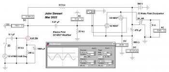
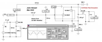
Here is the SE 6BX7 from Electra Print It has the same prob;em of very high plate dissipation.
vtadiy's online loadline calculation indicates a pair of 6BX7 triodes on a common triode cathode resister
should be Rk ~ 800R, a large difference from the Electra Print Schematics. Something to Sim later.
vtadiy's online loadline calculation indicates a pair of 6BX7 triodes on a common triode cathode resister
should be Rk ~ 800R, a large difference from the Electra Print Schematics. Something to Sim later.
Attachments


I didn’t even catch that it was a 6j6 instead of the 6j5 I was expecting. The amp I had used a 6j5 per side and sounded quite good. Not sure what kind of feedback it had.I would ditch the 6J6. That's an RF type that's specified for use as a mixer up to 600MHz. Mixing means nonlinear. Save the 6J6s for your RF projects. I would use a 6AU6 as a pseudotriode for the gain stage. (The 6J5 is also a good choice, but at the sacrifice of some gain. It's also an Octal type.) More linear, and the gain is roughly the same. I would also include some gNFB.
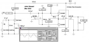
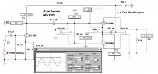
Here are the Sims where the 6BX7 cathode resister has been increased so that plate dissipation is under control.
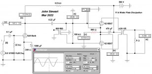
And sims for a 6J5 driver instead of the 6J6, A 6J5 plate resister of say 22K would be a better match,
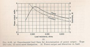
Max power for an ideal triode occurs when Rl = 2rp. But in practice with real triodes max power is more like when Rl = 2.5rp.
Most designers would go to ~Rl = 4rp or greater to reduce distortion & improve damping factor.
It looks like the designers at Electra Print went for Max Power.
The curve of power & distortion vs Rl is common for any ordinary triodes. Only the scale factors are different.
And sims for a 6J5 driver instead of the 6J6, A 6J5 plate resister of say 22K would be a better match,
Max power for an ideal triode occurs when Rl = 2rp. But in practice with real triodes max power is more like when Rl = 2.5rp.
Most designers would go to ~Rl = 4rp or greater to reduce distortion & improve damping factor.
It looks like the designers at Electra Print went for Max Power.
The curve of power & distortion vs Rl is common for any ordinary triodes. Only the scale factors are different.
Attachments
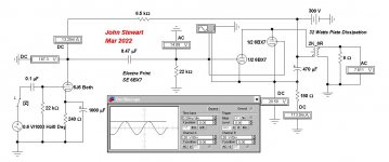
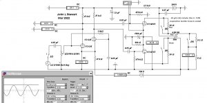
Hi John, how do you rate that phase splitter in the Electraprint PP amp? One hardly ever sees a transformer being used in phase splitter duty.
I used a transformer in that simulation, Electronic Workbench has no tapped choke model.
So a 100H, high impedance OPT with the secondary open works.
Back in the 30s the tapped choke made a lot of sense, tubes were expensive, iron cored inductors were not.
I don't recall ever seeing a tapped choke. And as far as I recall Hammond had none in their product line.
But if you asked back then they would wind anything you wanted, I had many specials made during the time I worked in the lab.
And until the late 30s there were no common small signal twin triodes.
Times change & the devices available to us change too. So I'm a fan of using a negative PS to power differential amplifiers.
Easy to do now & has been for more than 60 yrs.
The PP 6BX7 amp attached uses the 6J6 in a simple, long tailed arrangement. With ~1.3V at the input grid there is about 5.5 watts of audio.
The -150V is simply supplied off the normal PT with sufficient filtering. Less distortion & better damping could be got with an OPT of higher load.
Attachments
Here is the SE 6BX7 from Electra Print It has the same prob;em of very high plate dissipation.
vtadiy's online loadline calculation indicates a pair of 6BX7 triodes on a common triode cathode resister
should be Rk ~ 800R, a large difference from the Electra Print Schematics. Something to Sim later.
Thanks for doing this. I have to confess that I ordered the 2k:8 5w 70ma OPT for this project from Jack a while back, I have not yet built it though. Now I'm glad I didn't. Thinking I should use 6SN7 instead of 6J6 and adjust cK as you've shown.
Related to this, what is the difference between using a transformer in the amp vs one in the preamp for phase splitting? My preamp has an output transformer and balanced outputs.Hi John, how do you rate that phase splitter in the Electraprint PP amp? One hardly ever sees a transformer being used in phase splitter duty.
Balanced line & transformers are common in the broadcast industry where they prevent ground loops.Related to this, what is the difference between using a transformer in the amp vs one in the preamp for phase splitting? My preamp has an output transformer and balanced outputs.
But not much in common consumer audio, altho it can be done,
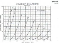
Looking at the plate family of each section of the 6BX7, the rp looks like approximately One K.Thanks for doing this. I have to confess that I ordered the 2k:8 5w 70ma OPT for this project from Jack a while back, I have not yet built it though. Now I'm glad I didn't. Thinking I should use 6SN7 instead of 6J6 and adjust cK as you've shown.
So connected in parallel that would put the combined rp at 500R. Your OPT is 4 times that, a good load for triode connexion.
Makes me think you are good to go, should work OK for you.
The plate dissipation of ~10W on the schematic is at no signal. For a Class A Amp some of that appears in the output audio.
So when the amp is performing the dissipation in the tube is less.
Looking at the plate family of each section of the 6BX7, the rp looks like approximately One K.
So connected in parallel that would put the combined rp at 500R. Your OPT is 4 times that, a good load for triode connexion.
Makes me think you are good to go, should work OK for you.
The plate dissipation of ~10W on the schematic is at no signal. For a Class A Amp some of that appears in the output audio.
So when the amp is performing the dissipation in the tube is less.
Thanks again, Jack sized the OPT as "5 to 10 watts" so I assume that means he overbuilt it a little. There are so many great 6SN7 front ends I will probably breadboard three of them then choose the one I like best, an SRPP, the "Franks" 6SN7 preamp in the archives here, then maybe try a single stage 6SN7 or two 6J5 since I'll have 4 holes in the chassis. Basically do it by ear and with the distortion analyzer and pick the front end that sounds and matches best. The microphonics of 6J6 puts me off.
Thanks again, Jack sized the OPT as "5 to 10 watts" so I assume that means he overbuilt it a little. There are so many great 6SN7 front ends I will probably breadboard three of them then choose the one I like best, an SRPP, the "Franks" 6SN7 preamp in the archives here, then maybe try a single stage 6SN7 or two 6J5 since I'll have 4 holes in the chassis. Basically do it by ear and with the distortion analyzer and pick the front end that sounds and matches best. The microphonics of 6J6 puts me off. And yes looking at numerous other 6BX7 schematics everyone uses around 1.5k so 800 paralleled, the Electra Print schematic is indeed not the best operating point here.
Better use 6sl7 as input tube, then concertina splitter, float the entry tube in grid bias.
I obtain conservatively 0.5%thd (if I can remember well) at 8 Watts from pp 6bl7 similar to 6bx7, really makes me want to build another version with // 6bx7, (4 tubes per channel) thd is very low otherwise. I did everything I could to maximize the power and keep the sound very smooth.
I obtain conservatively 0.5%thd (if I can remember well) at 8 Watts from pp 6bl7 similar to 6bx7, really makes me want to build another version with // 6bx7, (4 tubes per channel) thd is very low otherwise. I did everything I could to maximize the power and keep the sound very smooth.
Given the experience, multiple simulations & actual measured test results I got on both
6BX7 & 6BL7, those results don't make sense. How were the measurements made & with what equipment?
Do you have a schematic we can see?
THX
6BX7 & 6BL7, those results don't make sense. How were the measurements made & with what equipment?
Do you have a schematic we can see?
THX
Cannot be class A, of course. But the 6BX7 can take up 500V on the plate. Check 390V/10mA per tube out (Bias -40V). Using something like 18K plate-to-plate should be able to make 8-9W with 80V grid-to-grid drive. Run a sim and see if that is possible.
At that operating point plate resistance should be some 3-3.5K and gm about 2.5-3 mA/V for a gain around 9.
At that operating point plate resistance should be some 3-3.5K and gm about 2.5-3 mA/V for a gain around 9.
I'll run a Sim, but at those conditions the 6BX7 / 6BL7 triodes are far into Class AB.
Might be a lot of 3H due to cross over distortion. All my tests were in Class A.
And no use at all of Cookes Variable Constant to get wished for results.😀
Would still like to see the posters schematic.
Might be a lot of 3H due to cross over distortion. All my tests were in Class A.
And no use at all of Cookes Variable Constant to get wished for results.😀
Would still like to see the posters schematic.
I took an EICO ST70 and converted it to parallel push pull 6BX7. I added a 6H choke for choke input to get proper B+ for the 6BX7, replaced the 12AX7 with a 6DJ8 used 100K IIRC for the new plate load - that kept voltage very close to where it was at the 12ax7's p;late which is directly connected to the 6SN7 inverter. Removed the loop feedback. A very fun amp. (EICO's ST70 was great from the getgo - wideband output transformers - its every bit as good as their HF87 - - and looked nicer. \
I found the test results, I used real speaker loads and a dummy load, used quantum asylum thd analyzer and scope ( I have 2 of there machines) , 0.5 % thd is at 4 watts into 8R, no difference with real speaker load at 6 R from my measurements. https://quantasylum.com/collections/frontpage/products/qa403-audio-analyzer , 1 % thd is reached at 8 wattsGiven the experience, multiple simulations & actual measured test results I got on both
6BX7 & 6BL7, those results don't make sense. How were the measurements made & with what equipment?
Do you have a schematic we can see?
THX
Last edited:
For the PP 6BL7 & 6BX7 most of the circuit heat dissipation occurs in the same tube, the PP output.
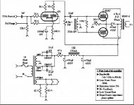
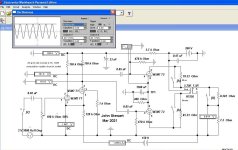
Here is another approach to a small amp using a pair of small octal based tubes.
A better way with common small octal based double triodes uses a pair of 6EA7 or 6EM7 in PP.
That way the required plate power is split between two tubes & total dissipation possible is increased.
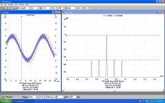
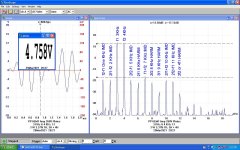
This one managed 7W audio on a 260V supply, all in Class A. 👍
The differential driver uses the hi mu triodes while the PP output is on the lo mu triodes of each tube.
The diff amp tail is a simple 120K resitor taken to -150V.
The triple switch 'A' allowed measuring the effect of the OPT winding resistances.
The scope traces show DC level on G1 of one of the output tubes so that overdriving can be detected.
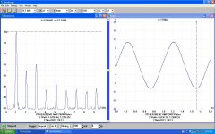
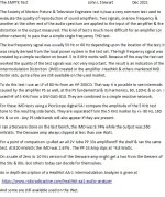
Two kinds of IMD measurement are used. The 3.4 method was devised by Graeme Cohen, his paper
is included for your pleasure.😀
I did this one about 3yrs ago, all results posted here on DIY.
Here is another approach to a small amp using a pair of small octal based tubes.
A better way with common small octal based double triodes uses a pair of 6EA7 or 6EM7 in PP.
That way the required plate power is split between two tubes & total dissipation possible is increased.
This one managed 7W audio on a 260V supply, all in Class A. 👍
The differential driver uses the hi mu triodes while the PP output is on the lo mu triodes of each tube.
The diff amp tail is a simple 120K resitor taken to -150V.
The triple switch 'A' allowed measuring the effect of the OPT winding resistances.
The scope traces show DC level on G1 of one of the output tubes so that overdriving can be detected.
Two kinds of IMD measurement are used. The 3.4 method was devised by Graeme Cohen, his paper
is included for your pleasure.😀
I did this one about 3yrs ago, all results posted here on DIY.
Attachments
-
 6EM7 PP Amp Mar.jpg143.9 KB · Views: 50
 -
 6EM7 PP Amp Mar.jpg143.9 KB · Views: 46
 -
 PP 6EA7 Amp 3 Watts.JPG117.4 KB · Views: 45
 -
 PP 6EA7 Amp 7 Watts.JPG119 KB · Views: 39
 -
 PP 6EA7 Amp One Watt.JPG109.9 KB · Views: 39
 -
 PP 6EM7 Amp One Watt IMD.JPG116.2 KB · Views: 39
 -
 SMPTE Test System.jpg147.3 KB · Views: 54
 -
 6EA7 6EM7 Amp 3W 3&4 KHz IMD Captions.jpg191 KB · Views: 56
 -
3-4.ratio.distortion.measurement Graeme Cohen 2008.pdf815.2 KB · Views: 42
what would be interesting is to use 4x 6bx7 because we know it sounds super smooth and more power would increase the fidelity, reduce some 2nd harmonics and make it sound more accurate
- Home
- Amplifiers
- Tubes / Valves
- What is the probable configuration of a 6BX7 amp I used to own?