How about that Q2?
Can it be pnp?
Has emitter and collector to be changed?
And how about C4 value?

Thanks!
Z
Can it be pnp?
Has emitter and collector to be changed?
And how about C4 value?
Thanks!
Z
Almost everything is not good. Too many to mention.
If u r thinking of assembling it, don't.
Better go for better designs.
Gajanan Phadte
If u r thinking of assembling it, don't.
Better go for better designs.
Gajanan Phadte
Agree on that. For simple, safe and good sounding stuff, Look at DestroyerX ( Carlos') DX amplifier : http://users.tpg.com.au/users/gerskine/dxamp/
Last edited:
There is nothing really wrong with that design at all.
"How about that Q2?"
What about it, it's one have of the diff input pair.
"Can it be pnp?"
It must be the same as Q1, it's one half of the diff input pair.
"Has emitter and collector to be changed?"
No, it's one half of the diff input pair.
"And how about C4 value?"
47µF~100µF would be a good value, with R8 and R9 it's part of the bootstrap CCS for Q3.
R2 bootstraps the input impedance (makes it higher).
This is really a common and ordinary amplifier. Use a 10Ω+0.1µF Zobel on the output to ground (before the fuse).
HI!
Thanks for advice.
Now I'm wondering Q1. Where comes its collector current?
I draw the schematic so that positive side is upper and it's now easier to understand, but Q1 seems to be quite weird on ordinary differential amp.
J
Thanks for advice.
Now I'm wondering Q1. Where comes its collector current?
I draw the schematic so that positive side is upper and it's now easier to understand, but Q1 seems to be quite weird on ordinary differential amp.
J
Now I'm wondering Q1. Where comes its collector current? J
R5 & Base Emmiter of Q3
Doc
DJK you are right, there is nothing wrong with the design, it is just not drawn nicely that is all. The person who drew the schematic forgot to put a ground connection between the 4700uF power supply caps.
Last edited:
almost class B ... no thermal compensation .... thermal run away is waiting around the corner ...if pushed it will fail .... at 42+42 volts i will be pushed any way
It's class AB+B.
Adjust R1 to about 0.34V across the base of each output.
Attach D4, D5 to the heatsink for the drivers (if any).
Adjust R1 to about 0.34V across the base of each output.
Attach D4, D5 to the heatsink for the drivers (if any).
that IS the most bizarre way i've seen a diff amp drawn. this looks like something designed for a cheap guitar amp or a console "hi-fi" in the 70's.
btw Q4 in the above schematic is the constant current source for the diff amp. the diodes D4, D5 should be attached to the heat sink for thermal stability.
as for odd ways of drawing diff amps, i always thought the way they were drawn in some of National Semiconductor's data sheets was rather strange.
Attachments

Last edited:
Want a crazy diff pair?
Find a McIntosh schematic for an MA6100, MC2100 or MC2300.
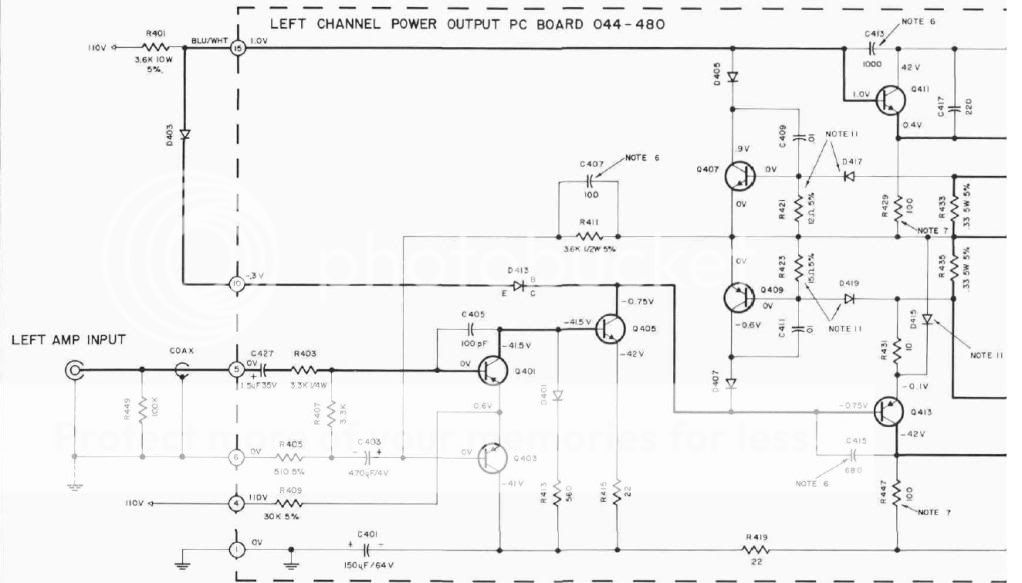
Yes, the diff pair runs on -41V and +110V.
Find a McIntosh schematic for an MA6100, MC2100 or MC2300.
Yes, the diff pair runs on -41V and +110V.
Last edited:
Any LTP diff pair can be run from asymmetrical rail supplies.
The collector/drain loads are fed from the Full Rail Voltage.
The Tail simply needs a Current. This current can be provided from a variety of voltages of much lesser voltage than Full Rail Voltage.
The collector/drain loads are fed from the Full Rail Voltage.
The Tail simply needs a Current. This current can be provided from a variety of voltages of much lesser voltage than Full Rail Voltage.
An infinitely high voltage rail with an infinitely high value resistor makes a good CCS.
McIntosh always used very high voltages for their LTP, their preamps are the same way. The Vas also uses a high value resistor to a high voltage rail.
This is good practice, but most people will not have seen a CCS done this way (or the schematics drawn this way).
McIntosh always used very high voltages for their LTP, their preamps are the same way. The Vas also uses a high value resistor to a high voltage rail.
This is good practice, but most people will not have seen a CCS done this way (or the schematics drawn this way).
- Status
- Not open for further replies.
- Home
- Amplifiers
- Solid State
- What is sucking in this wiring?