Member
Joined 2009
Paid Member
There is a ‘art and craft’ use to nested feedback. Because it uses up open loop gain in a local loop there is less available for the global loop. The result changes the harmonic profile of the amplifier, it’s variation under loading, interaction with the speaker etc. Anybody who’s tuned Cdom in a classic RAC/Blameless amp will know how small changes can impact the sound, all the while still being inside a stable operating envelope. Looking for examples - check out Hugh Dean’s amplifiers, somebody who mastered the art & craft.
Damir,
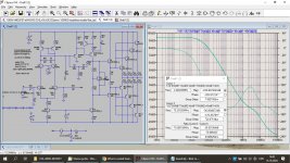
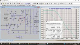
I implemented your OITPC into a more mundane circuit diagram, of which the settling time was shown here:
What is nested feedback, how it realy works and some examples...
and more details here:
Simulating single pole vs. Transistional Miller Compensation (TMC)
Having halved the two 200pF caps in value from the TPC and reduced the TPC resistor in between to gnd from 2k to 400R and finally having connected the LS output through a 100pF cap to the input of the VAS, I got the settling time changed to what's shown below.
What a difference this makes !
At the same time, THD at 1Khz and 3Khz is still 17dB below the Single Pole version just like the TPC, but at 10Khz where improvement of the TPC was only 8 dB, the OITPC is now 14dB better as the Single Pole version.
I don't know what this all means to the perceived sound reproduction, but it seems that OITPC betters Single Pole in every aspect.
Bravo for Damir, I'm very impressed.
Hans
P.S. Adding a cap parallel to the VAS emitter resistor did not improve things in this case.
Attachments

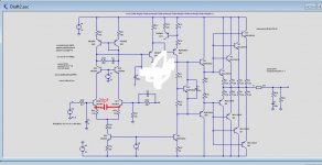
Start the correction from the base Q15 to the output of the amplifier.The distortion will be reduced !!!
Of course, here they are both, the single pole and the OITPC version.
Note that I made it as hard as possible with a 4R load and no input filter.
Hans
Loop probe is missing.
Hi Hans,
I could not make run your loop probe, so I used probe from LTspice examples.
Attached two Loop Gain plots with different "Charry" cap (C9) connection, and I prefer to connect it to the TPC resistor(R25) not directly to Q15 base as it gives higher phase margin.
The cap parallel to the VAS emitter resistor increase phase margin too.
One suggestion, for optimal TPC is better to use unequal value for C4/C6.
I think it was explained in a thread about TPC vs TMC.
Attached two Loop Gain plot, with different C9 connection.
Damir
Attachments

Sorry your picture is a little illegible to me. What is the other end of C9 connected to in OITPC?
Damir,
I implemented your OITPC into a more mundane circuit diagram, of which the settling time was shown here:
What is nested feedback, how it realy works and some examples...
and more details here:
Simulating single pole vs. Transistional Miller Compensation (TMC)
Having halved the two 200pF caps in value from the TPC and reduced the TPC resistor in between to gnd from 2k to 400R and finally having connected the LS output through a 100pF cap to the input of the VAS, I got the settling time changed to what's shown below.
What a difference this makes !
At the same time, THD at 1Khz and 3Khz is still 17dB below the Single Pole version just like the TPC, but at 10Khz where improvement of the TPC was only 8 dB, the OITPC is now 14dB better as the Single Pole version.
I don't know what this all means to the perceived sound reproduction, but it seems that OITPC betters Single Pole in every aspect.
Bravo for Damir, I'm very impressed.
Hans
P.S. Adding a cap parallel to the VAS emitter resistor did not improve things in this case.
Hi Hans,
I could not make run your loop probe, so I used probe from LTspice examples.
Damir
It's a pity you couldn't make use of the Loop probe.
All you have to do is to unpack the zip file in the directory where the model is located.
It uses a slightly more sophisticated algorithm as the Middlebrook version from LTSpice.
But like always, there are more ways to get there where you want.
The circuit I used was not mine but from profdc9, so I wanted to change as little as possible.
In the Single Pole version it had a Cdom of 100pF.
That brought me to the version that I showed, that now had two 100pF caps, so for single pole, one cap has to be omitted or shortened.
When adding a cap to the Vas emitter resistor, phase margin stayed exactly the same, but the GBW doubled and there was some HF "wobbling" visible in the Settling graph that wasn't there without.
In your first example Phase Margin is even bigger with 94 degrees, but is that really needed with the already excellent settling behaviour ?
Hans
P.S. what load did you use at the LS output, because this was not shown.
I wanted to do that fast and there no big difference between Middlebrook version and that one, Bode plot is the same. You used different models names and I had to change that as in my kean4.bjt models file.
To use equal caps value in TPC is not optimal, as well in TMC.
I used 8 ohm load.
Attachments
There is a ‘art and craft’ use to nested feedback. Because it uses up open loop gain in a local loop there is less available for the global loop. The result changes the harmonic profile of the amplifier, it’s variation under loading, interaction with the speaker etc. Anybody who’s tuned Cdom in a classic RAC/Blameless amp will know how small changes can impact the sound, all the while still being inside a stable operating envelope. Looking for examples - check out Hugh Dean’s amplifiers, somebody who mastered the art & craft.
Which amplifier of Hugh Dean did you built?
Hi Damir,Attached two Loop Gain plots with different "Charry" cap (C9) connection, and I prefer to connect it to the TPC resistor(R25) not directly to Q15 base as it gives higher phase margin.
The cap parallel to the VAS emitter resistor increase phase margin too.
One suggestion, for optimal TPC is better to use unequal value for C4/C6.
I think it was explained in a thread about TPC vs TMC.
Attached two Loop Gain plot, with different C9 connection.
Damir
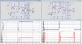
I tried different version, with unequal values for C4/C6, with C9 connected to Q15/R25, still without the VAS emitter Cap and last but not least your complete suggestion.
When changing the C4/C6 ratio, phase margin increased a bit at the cost of a worse settling, also not improving when I connected C9 to R25 instead.
Then I took your version that proved to be inferior in settling and gave only an insignificant 1.5dB improvement in THD@10Khz, which was to be expected because you increased the BW.
See Images below, simple OITPC version left and your suggestion at the right.
So all in all, my attempt may have been a lucky shot with only 2 caps and 1 resistor added to the Single pole version, but to my opinion the best version so far for this vehicle.
Hans
Attachments

Hans, you could try it with CFA (I prefer it over VFA).
Damir
Damir, I think you have made the most perfect CFA with OITPC.
How could I possibly improve on this design ?
But I’m very happy that you have made me aware of this two pole scheme.
Hans
Damir, I think you have made the most perfect CFA with OITPC.
How could I possibly improve on this design ?
But I’m very happy that you have made me aware of this two pole scheme.
Hans
Hans, you are so kind.
Nothing is perfect and some different approach could came with new ideas and solutions.
Best wishes, Damir
- Home
- Amplifiers
- Solid State
- What is nested feedback, how it realy works and some examples...