Feedback from VAS Output
Interesting that there is discussion of this nested feedback.
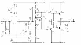
To date have been using resistive shunts to GND from the VAS output to reduce loop gain at lower frequencies. However, just recently, have been looking at the feasibility of returning these resistors back to the LTP feedback node instead. The thinking being that this could be make use of the feedback being wasted by the resistive shunts. Then I thought this feedback could come back from the drivers (2EF) therefore reducing VAS load. It all works but can't see any real performance gains in LTspice.
Can't help thinking I'm missing something??
Paul
Interesting that there is discussion of this nested feedback.
To date have been using resistive shunts to GND from the VAS output to reduce loop gain at lower frequencies. However, just recently, have been looking at the feasibility of returning these resistors back to the LTP feedback node instead. The thinking being that this could be make use of the feedback being wasted by the resistive shunts. Then I thought this feedback could come back from the drivers (2EF) therefore reducing VAS load. It all works but can't see any real performance gains in LTspice.
Can't help thinking I'm missing something??
Paul
I don't think 'artificially' lowering loop gain for low freqs with a resistive Vas load does anything good.
Your (stability etc) issues are at the high end of the band, not at the low end.
It s the old discussion: it does make the distortion graph look flat, but only because it brings up the lf distortion to the level of the hf distortions.
Why would you accept higher than necessary lf distortion just to have a graph that 'looks nice'??
Jan
Member
Joined 2009
Paid Member
The only benefit I can see is the ability to tailor the overall distortion profile, this means it's about 'sound' and not engineering the lowest distortion possible.
The only benefit I can see is the ability to tailor the overall distortion profile, this means it's about 'sound' and not engineering the lowest distortion possible.
Well I have a hard time to accept that an amp with 10 or 100 times more distortion at 100Hz in some way sounds 'better' than one that has the lowest possible distortion there, all other things being the same.
Listeners may prefer it, and that's a personal thing, but it's not in any objective way 'better'.
Jan
My reasoning (maybe misguided as I'm far from an experienced amp designer) as Bigun says is to tailor the distortion profile. Already have low enough THD (simulated) at 20Khz for my purposes. Even given up on 2 pole compensation for now. High ULGF is the goal.
But my real confusion is that the two approaches to reduce low frequency loop gain appear equivalent. Which does seem right to me. This I'd like to understand.
Paul
But my real confusion is that the two approaches to reduce low frequency loop gain appear equivalent. Which does seem right to me. This I'd like to understand.
Paul
Well I have a hard time to accept that an amp with 10 or 100 times more distortion at 100Hz in some way sounds 'better' than one that has the lowest possible distortion there, all other things being the same.
Done judiciously, the increases in distortion are nothing like 10 to 100 times, and there are other benefits to this phenomenon. You had the chance when you visited me in 2015, Jan, but you never even asked, rejecting the ideas as fallacious.
I did not offer, this was your prerogative. Nonetheless we enjoyed a good meal together.
Hugh
The main reason I'm using the VAS load resistors, referenced to ground - OPS input impedance shaping.
In BJT OPS, especially EF2, input impedance changes extensively in sync with the output current change, increasing distortion, especially IM. Assuming the VAS is designed for being capable of driving the higher load, those resistive shunts decrease the influence of OPS input impedance variance.
in my experience, nested feedback - assuming the loop gain around the OPS is decreased - works best with low-distortion OPS topologies / builds. I used it with my non-switching OPS.
In my case - internal feedback loop additionally loads the VAS stage and decreases the loop gain over OPS at the same time, providing slightly less control over the speakers.
Overall subjective effect - more pleasing bass representation.
It's deep, "velvet", elastic and less "dry" at the same time.
However, Jeff, for example, likes more controlled sound of Vertical CFA (higher loop gain, lower output impedance) better.
Rather individual thing.
Done judiciously, the increases in distortion are nothing like 10 to 100 times, and there are other benefits to this phenomenon. You had the chance when you visited me in 2015, Jan, but you never even asked, rejecting the ideas as fallacious.
I did not offer, this was your prerogative. Nonetheless we enjoyed a good meal together.
Hugh
Ahhh yes, I enjoyed that visit! We didn't talk all that much about audio, did we? People are more interesting 😉
I timed it all wrong, should have spend less time in Tassie and more in Melbourne. But so it goes.
Anyway, I'd really like to know about 'other benefits' because I can't see them!
Increasing distortion (or more generally non-linearity) at lower freqs to make them as large as the higher non-linearity at high freqs, WTF?? 😎
Jan
Last edited:
The main reason I'm using the VAS load resistors, referenced to ground - OPS input impedance shaping.
In BJT OPS, especially EF2, input impedance changes extensively in sync with the output current change, increasing distortion, especially IM. Assuming the VAS is designed for being capable of driving the higher load, those resistive shunts decrease the influence of OPS input impedance variance.
I agree to this, but it doesn't make things better. Making the influence of the driver input impedance lower by shunting it with an even lower impedance only increases the load of the Vas even further! Everything gets worse that way!
Jan
I agree to this, but it doesn't make things better. Making the influence of the driver input impedance lower by shunting it with an even lower impedance only increases the load of the Vas even further! Everything gets worse that way!
Jan
Jan, here is the thing - one of the causes of IM distortion is OPS input impedance CHANGE. This is a dynamic effect, a pretty complex modulation.
Making the load higher (impedance - lower), but more constant (less modulated), we may slightly increase THD at the low end, but decreases dynamic distortions, like IMD, in the whole audio range.
Which is more important, to my taste.
There are many other ways to stabilize the input impedance of the OPS - use CCSed drivers, add one more follower in front of the drivers and tame the additional phase shift (and shunt it again, but with higher value load)...
Better way is to use VAS gain for decreasing VAS output impedance (and linearity) simply using local NFB in VAS , resistor in hundreds kohm (in series with e.g 330n capacity) parallel to Cdom.
Better way is to use VAS gain for decreasing VAS output impedance (and linearity) simply using local NFB in VAS , resistor in hundreds kohm (in series with e.g 330n capacity) parallel to Cdom.
How to do this with a cascode VAS though?
Paul
Jan, here is the thing - one of the causes of IM distortion is OPS input impedance CHANGE. This is a dynamic effect, a pretty complex modulation.
Making the load higher (impedance - lower), but more constant (less modulated), we may slightly increase THD at the low end, but decreases dynamic distortions, like IMD, in the whole audio range.
Which is more important, to my taste...
Yes that is a good point,that may indeed be advantageous. Hmm, maybe I learned something again today ;-)
Thanks, Jan
The same way as in "simple" VAS , local NFB from VAS output to VAS input.How to do this with a cascode VAS though?
The same way as in "simple" VAS , local NFB from VAS output to VAS input.
Something to experiment with later.
Paul
Better way is to use VAS gain for decreasing VAS output impedance (and linearity) simply using local NFB in VAS , resistor in hundreds kohm (in series with e.g 330n capacity) parallel to Cdom.
Right, but you can also make the loop wider - just put that resistor between the VAS output and the amp's negative input. We come back to nested feedback configuration then - lower VAS output impedance plays its positive role again.
Hi everyone. Thank you very much for the explication. It has generated an interesting debate. I am not an expert in amplifier design. I'm just a hobbyist.
GE
GE
After reading the various post, here is indeed a definition of the value of R10 according to Hugh. R = 1M. It will be OK?
GE
Hi GE,
How did you come to 1M?
In fact, 1M will not really influence anything. Way too high value.

- Home
- Amplifiers
- Solid State
- What is nested feedback, how it realy works and some examples...