I must say It is superb that you not only do something that was written somewhere in the Internet, but you really see with oscilloscope a real picture what really happens in real live circuit.Thanks again for taking the time to help me out.
To see even further and deeper I use three devices - oscilloscope (of cause), then micro-voltmeter, and the third - audio spectrum (signal) analyzer (sound card + software, ARTA). That devices give me much complete and deep picture.
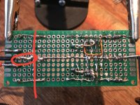
What am I missing here? The placement of the ground wire in post #14 and the wire in post 16 look identical. Yes there is a long solder tail in the first one. But the connection is at the crossing point of the wires or at most a mm past it. Could that mm make that much of a difference. The biggest change that I see is that the alligator clip is attached to a hot wire in post 16.
Thanks Osvaldo, it’s been an eye opening experiece.In those situations, think as you are the electrons inside the wire. Do you prefer a long way from job to house, as an example? Or do you prefer a short one? As inductances are acting as reactive elements, their "ways" are like you turn 90° at the corner in a direction apart from you way. So, again, do you prefer few turns at the corners or fewer ones
?
The main difference was in moving the connection from the CT so that it wasn’t any “further down the road” than the primary capacitors.
I wonder what the mechanism is that causes the spikes to form when there is a 1cm of overlap Of wire at this point?
Well done, @The Lord Flashheart - It's really like a kind of magic 🙂 , or in other words - you can't trust a Ground. Every point of ground wire is another.
I must say It is superb that you not only do something that was written somewhere in the Internet, but you really see with oscilloscope a real picture what really happens in real live circuit.
To see even further and deeper I use three devices - oscilloscope (of cause), then micro-voltmeter, and the third - audio spectrum (signal) analyzer (sound card + software, ARTA). That devices give me much complete and deep picture.
Cheers Vovk, this is an attempt to get back to basics. I came at this backwards in that I started off by trying to repair vintage hifi stuff and making things worse in the main rather than fixing stuff... 😀
I thought I had better start from the beginning and build circuits to try and understand amplifier design. Power supplies in general seem to be the starting point, one also ends up with a useful circuit or two at the end of it.
The main difference was in moving the connection from the CT so that it wasn’t any “further down the road” than the primary capacitors.
I wonder what the mechanism is that causes the spikes to form when there is a 1cm of overlap Of wire at this point?
Thats what I was trying to tell you in post 9.
The sharp short charging impulses into the smoothing caps mustn't get into the power supply after the smoothing caps or it will modulate the ground line causing havoc.
I designed a USB mixer pcb many years ago.
On test with inputs shorted there was 1 VAC on the output !
I traced it to noise in the ground line.
I reworked the pcb having a flow through the power supply rather than just all mixed together. This time there was negligible noise on the output.
While a wire might seem like a short circuit it is in reality a resistor and an inductor. So any current through it will generate a voltage across it.
All part of the fun of learning. If you had got it right first time by accident you wouldn't have learned anything.
Last edited:
Yes, it's fascinating. 🙂
I see what you all mean about flow, nothing quite like seeing it for oneself as you say.
I see what you all mean about flow, nothing quite like seeing it for oneself as you say.
- Home
- Amplifiers
- Power Supplies
- What is going on with my linear power supply?