I am using EXICON ECX10N20/ECX10P20 in an endstage. +/-16 Volt.
What would be the optimal adjusted quiescent bias for these transistors?
They are Lateral MOSFETs.
And do I use any gate resistors?
100 Ohm?
Or no resistors?
What would be the optimal adjusted quiescent bias for these transistors?
They are Lateral MOSFETs.
And do I use any gate resistors?
100 Ohm?
Or no resistors?
Gate resistors are essential for any MOSFET. They must be close to the gate pin to work.
100R won't have much negative effect on switching speed
100R won't have much negative effect on switching speed
Tried several class AB schematics with latfets, recommending usually 50-100mA bias with 100 ohm gate resistors.
I settled for 50 mA bias. It was a tiny bit better than 100 mA.
And the 100 Ohm resistors are in place! 🙂
And the 100 Ohm resistors are in place! 🙂

Laterals have a specific Id for zero tempco below which the tempco will be positive and above it the tempco becomes negative. I have no experience with exicons, the K1058 was around 125mA, slightly lower for the J162.I settled for 50 mA bias. It was a tiny bit better than 100 mA.
And the 100 Ohm resistors are in place! 🙂
Gate resistor is needed to suppress oscillation, 100r gate resistor is kind of small for them, may not be enough in case of clipping, difficult load or RFI. 330r - 680r would be safer. I've even seen others recommend ferrite beads.
I went back to 200 mA. I had this before I tested 50 mA.
200 mA gives better bandwidth and so I can reduce compensation and so lower dist is a result.
I still have to test 125mA or 150mA.
Maybe increase gate resistors to 220 Ohm.
VAS current is increased to 6mA. It was 2 mA before.
Better bandwidth with the current.
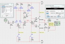
Here is the schematic. I have not built and will not do this.
I am just playing with SPICE and the built in Oscilloscope. Because I think this is fun 😀
200 mA gives better bandwidth and so I can reduce compensation and so lower dist is a result.
I still have to test 125mA or 150mA.
Maybe increase gate resistors to 220 Ohm.
VAS current is increased to 6mA. It was 2 mA before.
Better bandwidth with the current.
Here is the schematic. I have not built and will not do this.
I am just playing with SPICE and the built in Oscilloscope. Because I think this is fun 😀
Attachments
Last edited:
BTW I'd recommend adding back-to-back 10V--15V zeners between gate and source of each MOSFET otherwise they are not necessarily going to show their full levels of robustness - exceeding Vgs absolute maximum value can instantly destroy any MOSFET. I believe that Exicon's include some internal protection like this, but other latFETs are available and may be more vulnerable.
You can bias latFETs over a fairly wide range without massive changes in performance, for instance you might want to have less quiescent consumption and choose 30 to 50mA - there shouldn't be a sudden jump in distortion like with BJTs that are underbiased, just an gradual rise in distortion (in theory at least). However if you let the bias drop right down to 0mA you'll often see strong oscillations (well I do!) - I recommend setting the biasing without a load attached because of this.
And MOSFET bias drifts slowly over time due to ion migration effects in the gate oxide - its worth rechecking the bias every decade or so (sometimes just testing the heatsink temperature by hand after its been idle for a while will give a quick indication - an amp I build back in the '80's had drifted enough for one channel's heatsink to be noticably cooler than the other after a few decades of intermittent use - though I suppose the trimmers might have drifted (I don't think that amp used cermet trimmers).
One other observation is that 100mA is also about the current where the temperature coefficient of latFETs flip - less current and heat increase the bias, more current and heat reduces the bias - in other words its roughly the naturally stable point.
I'd be curious to know how many times you've mentioned Maplin amps since you've been on the forum 😜The old 1980's Maplin lateral mosfet amp 100ma was recommended.
I think the Maplin standard was minimalism (i.e. cheapest possible) whilst maintaining reliability- an excellent base formula for simple, knockabout, DIY disco sound quality as it happens and of course, very popular when everything else available to the DIY'er in the UK was comparatively complex, expensive, difficult to source and you needed to visit several stockists for specific parts. Here's a breakdown of a typical, though neither 150W nor home built stereo amp:
It's also been many years since Nigel's kits were in production. I think they were gone last century and Maplin itself closed their doors 5 years ago. The trading name is now recycled, since retailers never miss an opportunity to profit from sentiment or memories, do they?
It's also been many years since Nigel's kits were in production. I think they were gone last century and Maplin itself closed their doors 5 years ago. The trading name is now recycled, since retailers never miss an opportunity to profit from sentiment or memories, do they?
Last edited:
I bias my MOSFET stage to 2A idle (25V across the device)... It's a class A stage though.
50mA seems like a value good for a tube to me. I bias most of mine to 40mA these days.
My best advise for your particular stage is to scope the output and make it as low as you can without having a notch or crossover distortion. From what I understand about SS stuff is you want it just hot enough to eliminate that distortion. Any more bias current seems to be a waste?
Just my thoughts as a tube guy. Please tell me if I'm off the mark!
The simple Hitachi/Maplin design is immensely gratifying and a nice way to start audio DIY from scratch.I think the Maplin standard was minimalism (i.e. cheapest possible) whilst maintaining reliability
Furthermore, it was the perfect remedy for an old farth like me to survive boredom during the pandemic confinement.
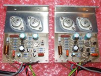
Could not believe how nice it sounds. PCB etched old school, designed by Prasi. 100mA bias.
Last edited:
I agree with how it likely sounds. I built 3 different sized, Hitachi design mosfet amps many years ago but unfortunately, this was before electronics hobby editors began to address hifi and audio sound quality at a serious level. Perhaps there would have been better information and less misunderstanding about lateral mosfets if authors had discussed the facts and reasons why both types of mosfets were different and often sounded different to BJTs - from a practical point of view, at least.
Lateral mosfest were made popular, especially down under, by David Tilbrook in the mid 80s. His AEM6000 is one of the best amps I ever built. Circuit update and PCB design by SuzyJ. I use it every day, 50mA bias. Unfortunately I am unable to find the three original 1986 AEM articles.

Jacques
You can get copies of the magazine from Silicon Chip Magazine, they hold the rights to AEM now.
Regards
Ejam
You can get copies of the magazine from Silicon Chip Magazine, they hold the rights to AEM now.
Regards
Ejam
Personally I never liked the Maplin / hitachi, I only mounted the Maplin to "put sound back into an unrecoverable chassis" and I had the whole HMA hitachi series (from the G2 to the 9500) because I I found it beautiful and well made but I am definitely from the "Plantefeve / Pass school" in A or AB but all LatFet.
Maybe I didn't delve into it enough...
@ Jacques antoine
Very "French" your construction 😁
Maybe I didn't delve into it enough...
@ Jacques antoine
Very "French" your construction 😁
The Maplin module has basically the same topology as the Hitachi HMA-7500. 7500 mk2 and above are very different beasts.
@huggygood
I would like to build one the medium power B or AB Plantefeve's designs. Which one would you recommend, possibly without hard-to-find input (J)FET?
I would like to build one the medium power B or AB Plantefeve's designs. Which one would you recommend, possibly without hard-to-find input (J)FET?
- Home
- Amplifiers
- Solid State
- What is a good BIAS for EXICON lateral MOSFETs?