Adding BJT version with servo....
Simulated THD is 0.002% . With a nice distortion profile and low noise.

Thanks
Mallik
Simulated THD is 0.002% . With a nice distortion profile and low noise.
Thanks
Mallik
Just a word on pursuing of the absolute lowest circuit THD. Most audio circuits THD performance is orders of magnitude beneath the threshold of audibility. At some point, other circuit parameters become more important for a given circuit. Such as the dynamic behavior for DAC I/V circuits. Also, limiting unnecessary circuit complexity becomes important unless one is an experienced engineer. Pursuit of perfection of a certain parameter can be fun for it’s own sake, but the benefit decreases rapidly, and the risk of technical failure increases rapidly.

H
HAYK
The 16bit PCM can have THD down to -96db or 0.0015%. First Philips 16bit DAC the1541 could go down -95db. The AD1862 with 20bit hardly reaches -98db. The IV converter must be maximum 1/2LSB that is 0.00075% noise included if the 16bit resolution to be respected.
Whether the human ears do hear or not is not the question as the DAC is to be considered as a precise sensor.
The distortion measurements with simulators are only relative values intended to push the design to its best. In real world the story is different, the input current source is not a current source. It is voltage and resistor both variable with the code. The input impedance with act nonlinearly, the offset voltage and current will be modulated with varying resistor. A quick estimation for 16bit gives a relative input impedance to be 32k times smaller than the IV resistance. If 3.2k is the resistance, the input impedance should be less than 0.1 ohm to be less than 1LSB for 16bit resolution.
See comparative measurements of different IVs
https://www.diyaudio.com/community/threads/dac-i-v-measurements.395738/
H
HAYK
This is 4//×2 common base IV without feedback. The paralleled transistors must be matched to Ic/Vbe. From a lot of 50 transistors can for sure get matched.
It has 0.1 ohm input impedance, 0.0007%THD but with 1vp, it goes to 0.003% with 3vp I need to solve it. The current sources have a common potentiometer to adjust the output offset and of course a servo for the input.

It has 0.1 ohm input impedance, 0.0007%THD but with 1vp, it goes to 0.003% with 3vp I need to solve it. The current sources have a common potentiometer to adjust the output offset and of course a servo for the input.
Attachments
We disagree here. What the human ear perceives is exactly the question. Perhaps, the most important fact to keep in mind is that the application is for human hearing, and the circuit’s parametric figures are only in a support role for serving that application. The application does not require the DAC to be a perfect sensor. Considering it to be that might potentially even prove counter-productive. Pursuit of further orders of magnitude reduction in THD beneath the threshold of human audibility for example, does not in itself, benefit the intended application. To my thinking, pushing a design to be its ‘best’ is a holistic endeavor, beginning from an application overview, and ending with implementation concerns, including cost.The 16bit PCM can have THD down to -96db or 0.0015%. First Philips 16bit DAC the1541 could go down -95db. The AD1862 with 20bit hardly reaches -98db. The IV converter must be maximum 1/2LSB that is 0.00075% noise included if the 16bit resolution to be respected.
Whether the human ears do hear or not is not the question as the DAC is to be considered as a precise sensor.
The distortion measurements with simulators are only relative values intended to push the design to its best. In real world the story is different, the input current source is not a current source. It is voltage and resistor both variable with the code. The input impedance with act nonlinearly, the offset voltage and current will be modulated with varying resistor. A quick estimation for 16bit gives a relative input impedance to be 32k times smaller than the IV resistance. If 3.2k is the resistance, the input impedance should be less than 0.1 ohm to be less than 1LSB for 16bit resolution.
See comparative measurements of different IVs
https://www.diyaudio.com/community/threads/dac-i-v-measurements.395738/
In general, the pursuit of objectively perfecting parameters far beyond meeting an application’s requirement is gratuitous engineering in any context. It may be intellectually stimulating or fun for the engineer, but it’s gratuitous none the less. Which is especially concerning, if other circuit parameters are potentially not beneath the threshold of audibility. Such as slew rate limiting for audio DAC I/V circuits, just for an example. Or, if the pursuit of further reducing some already inaudible parameter begins to significantly complicate the circuit design, needlessly adding risk of failure in either design, and in construction.
Since this is a hobby activity, however, pursuing something out of intellectual curiosity, or challenge, or just for the fun of it are all worthwhile reasons. If you are fully knowledgable and experienced in what you are doing, then my advice certainly does not pertain to you. It was not targeted at anyone in particular, and only was general advice to whomever was following the thread.
H
HAYK
HIFI, as the French call it chain, is the product of stages. Nowadays we have eliminated the preamp and tone control to let only DAC, volume control, amp,speaker. The main coloring (distorting) bottleneck element before digital, was the record pick up cartridge. The best in late 70's was Shure V MKIII, with 2%2H, 0.5%3H, 3%IMD, used mainly in radio stations.
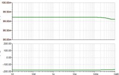
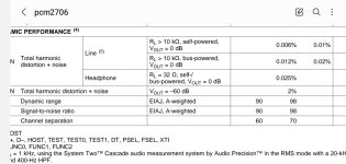
Nowadays, one can buy a decent 16bit DAC pcm2706 based for less than $15 with 0.006% THD.
DIYs decided to go NOS, but use very linear DAC ones with higher bit counts. To get still more linear, they stack in // many of these expensive components to get still better linearity.
Say that all this effort of cost and time, is to get as good sounding as Shure V could do?
If the DAC is precise, it can always be degraded by software, to sound as that particular tube amp or it can be buffered with distorting stage as Shure cartridge does.
DIYs decided to go NOS, but use very linear DAC ones with higher bit counts. To get still more linear, they stack in // many of these expensive components to get still better linearity.
As one of the DIYers who stack DACs (from TDA1387 through to PCM58), its not to get better linearity. Rather lower noise.
The 16bit PCM can have THD down to -96db or 0.0015%.
You are mixing up THD with THD+N again, and forgetting the 10 dB log10(3/2) term. There is no theoretical limit to how low the THD can go, only the THD+N.
H
HAYK
PCM2706 DS says 0.006% THD+N. S/ N, A weighted 98db.
S/N to be 95db no weighted it is 0.0018%.
THD =0.0042%
The PCM1704 has a S/N A weighted 120db
THD+N 0.0008%.
N=0.00017% non weighted.
THD=0.00053%.
If // is only for noise reduction, does it worth to // 7 of it as in a Accuphase DAC?
S/N to be 95db no weighted it is 0.0018%.
THD =0.0042%
The PCM1704 has a S/N A weighted 120db
THD+N 0.0008%.
N=0.00017% non weighted.
THD=0.00053%.
If // is only for noise reduction, does it worth to // 7 of it as in a Accuphase DAC?
Attachments
If // is only for noise reduction, does it worth to // 7 of it as in a Accuphase DAC?
When I took a look at an Accuphase multiple PCM63 DAC schematic quite recently, I figured that if lower noise really was the aim of having so many paralleled DACs, the implementation didn't achieve that very well. So it could just be that Accuphase uses multiple DACs for marketing purposes.
@HAYK,
Maybe, think of Marcel’s correct point in the following, over-simplified way. A 1-bit DAC inherently gives perfect differential linearity, as two points can only define a strait line. The problem comes that while giving perfect linearity, the quantization noise of a 1-bit DAC is only about 6dB below the signal. You can see from this extreme example, how a DAC could have both perfect linearity (zero distortion), and high (quantization) noise. This is why noise-shaping is critical for today’s lower bit-depth based quantizer audio DACs.
Maybe, think of Marcel’s correct point in the following, over-simplified way. A 1-bit DAC inherently gives perfect differential linearity, as two points can only define a strait line. The problem comes that while giving perfect linearity, the quantization noise of a 1-bit DAC is only about 6dB below the signal. You can see from this extreme example, how a DAC could have both perfect linearity (zero distortion), and high (quantization) noise. This is why noise-shaping is critical for today’s lower bit-depth based quantizer audio DACs.
Last edited:
H
HAYK
I reached to a good result. It has now 0.00025% THD for 3vp and 12uv noise with the same 0.1 ohm input impedance. Most of the noise is generated by the mosfets but I don't know any low noise ones. I had to forget about CCS as the lowest noise is 2x25uv by dn2540.

MOSFETs are always rather noisy but you can mitigate that by employing them in a low noise gain circuit. For example - used as a cascode where the impedance on the source is much higher than that on the drain.
- Home
- Source & Line
- Digital Line Level
- What input impedance for R2R I/V converter?